
Computer Hardware User's Guide

Configuration
10-10
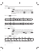
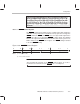
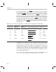
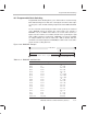
Table 10–1 describes the bits in the STRBO, STRB1, and the IOSTRB control
registers.
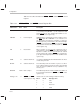
Table 10–1. STRB0, STRB1, and IOSTRB Control Register Bits
Abbreviation
Reset
Value
Name Description
HOLDST 0 Hold status bit This bit signals whether the port is being held (HOLDST = 1),
or is not being held (HOLDST = 1). This status bit is valid
whether the port has been held through hardware or soft-
ware.
(STRB0 control register only)
NOHOLD 0 Port hold signal NOHOLD allows or disallows the port to be held by an exter-
nal HOLD
signal. When NOHOLD = 1, the ’C3x takes over
the external bus and controls it, regardless of serviced or
pending requests by external devices. No hold acknowledge
(HOLDA
) is asserted when a HOLD is received. However, it
is asserted if an internal hold is generated (HIZ = 1).
(STRB0
control register only)
HIZ 0 Internal hold When set (HIZ = 1), the port is put in hold mode. This is
equivalent to the external HOLD
signal. By forcing the high-
impedance condition, the ’C3x can relinquish the external
memory port through software. HOLDA
goes low when the
port is placed in the high impendance state.
(STRB0 control
register only)
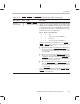
SWW 11 Software wait mode In conjunction with WTCNT, this 2-bit field defines the mode
of wait-state generation.
WTCNT 111 Software wait mode This 3-bit field specifies the number of cycles to use when
in the software wait mode for the generation of internal wait
state. The range is 0 (WTCNT = 0 0 0) to 7 (WTCNT = 111)
H1/H3 cycles.
BNKCMP 10000 Bank compare This 5-bit field specifies the number of MSBs of the address to
be used to define the bank size.
(STRB0 and STRB1 control
registers only)
Data type size 11 (STRB0 and STRB1
control registers only)
Indicates the size of the data type written in memory.
Bit 17 Bit 16 Data Type Size
008 bit
0 1 16 bit
1 0 Reserved
1 1 32 bit