
Computer Hardware User's Guide

Configuration
10-7
TMS320C32 Enhanced External Memory Interface
10.3 Configuration
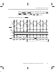
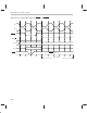
To access 8-, 16-, or 32-bit data (types) from 8-, 16-, or 32-bit wide memory, the
memory interface of the ’C32 device uses either strobe STRB0
or STRB1 with
four pins each. These pins serve as byte-enable and/or additional-address pins.
In conjunction with a shifted version of the internal address presented to the exter-
nal address, the ’C32 can select a single byte from one external memory location
or combine up to four bytes from contiguous memory locations. The behavior of
these pins is controlled by the external memory width and the data type size. The
selected data size also determines the amount of internal-to-physical address
shift. You can assign these values to the ’C32 memory interface through bit fields
in the bus control registers.
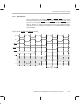
10.3.1 External Interface Control Registers
The following sections describe the bus control registers used to manipulate
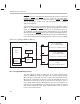
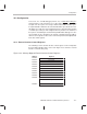
the byte addressability features of the ’C32. Figure 10–3 shows the external
interface control memory map.
Figure 10–3. Memory-Mapped External Interface Control Registers
Address Register
808060h
IOSTRB
control
808061h Reserved
808062h Reserved
808063h Reserved
808064h STRB0 control
808065h Reserved
808066h Reserved
808067h Reserved
808068h STRB1 control
808069h Reserved
.
.
.
80806Fh Reserved