
Computer Hardware User's Guide

Memory Interface Control Registers
9-8
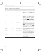
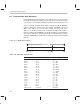
Table 9–3. Primary-Bus Control Register Bits
Abbreviation Reset Value Name Description
HOLDST 0 Hold status bit This bit signals whether the port is being
held (HOLDST = 1) or is not being held
(HOLDST = 0). This status bit is valid
whether the port has been held through
hardware or software.
NOHOLD 0 Port hold signal NOHOLD allows or disallows the port to be
held by an external HOLD
signal. When
NOHOLD = 1, the ’C3x takes over the
external bus and controls it, regardless of
serviced or pending requests by external
devices. No hold acknowledge (HOLDA
) is
asserted when a HOLD
signal is received. It
is asserted if an internal hold is generated
(HIZ = 1).
HIZ 0 Internal hold When set (HIZ = 1), the port is put in hold
mode. This is equivalent to the external
HOLD
signal. By forcing a high-impedance
condition, the ’C3x can relinquish the exter-
nal-memory port through software. HOLDA
goes low when the port is placed in the high-
impedance state.
SWW 11 Software wait mode In conjunction with WTCNT, this 2-bit field
defines the mode of wait-state generation.
(See Table 9–5.)
WTCNT 111 Software wait mode This three-bit field specifies the number of
cycles to use when in software wait mode for
the generation of internal wait states. The
range is 0 (WTCNT = 0 0 0) to 7 (WTCNT=1
1 1) H1/H3 cycles. (See Section 9.4.)
BNKCMP
10000 Bank compare This 5-bit field specifies the number of MSBs
of the address to be used to define the bank
size. (See Table 9–6.)