
Computer Hardware User's Guide

Memory Interface Signals
9-5
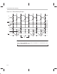
TMS320C30 and TMS320C31 External-Memory Interface
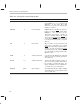
Table 9–2. Expansion Bus Interface Signals
Signal Type
†
Description
Value
After Reset
Idle Status
MSTRB O/Z Expansion bus memory access strobe 1 1
IOSTRB O/Z Expansion bus peripheral-access strobe 1 1
XR/W
O/Z Specifies memory (active high) or write (active
low) mode
11
XRDY
I Indicates external expansion interface is ready
to be accessed
NA
‡
Ignored
XA (12–0) O Expansion address bus. When the expansion
bus address lines are not in high-impedance
state due to HOLD
signal, they keep the last
external expansion bus access.
HI Address of last external
expansion bus access
XD (31–0)
I/O/Z Expansion data bus. These signals go to high-
impedance between write accesses.
HIZ HIZ
†
I Input
O Output
Z High impedance
‡
NA means not affected.