
Computer Hardware User's Guide

Memory Interface Signals
9-4
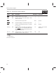
Table 9–1. Primary Bus Interface Signals
Signal Type
†
Description
Value
After Reset
Idle Status
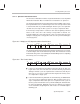
STRB O/Z Primary interface access strobe 1 1
R/W O/Z Specifies memory read (active high) or write
(active low) mode
11
HOLD
I Hold external memory interface NA
‡
Ignored
HOLDA
O/Z Hold acknowledge for external memory interface 1 1
RDY
I Indicates external primary interface is ready to
be accessed
NA
‡
Ignored
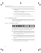
A (23–0) O/Z Primary address bus. When the primary bus
address lines are not in high-impedance state
due to HOLD signal, they keep in the last exter-
nal primary bus access.
HI Address of last external
bus access
D (31–0)
I/O/Z Primary data bus. These signals go to high-
impedance between write accesses.
HIZ HIZ
†
I Input
O Output
Z High impedance
‡
NA means not affected.