
Computer Hardware User's Guide
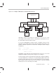
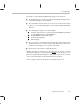

XF0 set as an
output pin and
XF1 set as an
input pin
XF1 sampled
XF0 driven low
and XF1 sampled
XF0 pin
driven high
XF1 pin
sampled
XF0 pin
driven low
Interlocked Operations
7-20
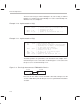
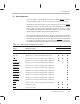
Example 7–13. Pipeline Delay of XF Pin Configuration
Pipeline Operation
PC Fetch
Decode Read Execute
n LDI 2h, IOF
n+1 NOP LDI 2h, IOF
n+2 NOP NOP LDI 2h, IOF
n+3 LDII *AR1, R1 NOP NOP LDI 2h, IOF
n+4 LDII *AR1, R1 NOP NOP
n+5 LDII *AR1, R1 NOP
n+6 LDII *AR1, R1
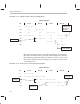
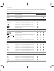
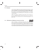
STFI and STII instructions drive the XF0 pin high during its execution phase.
LDFI, LDII, and SIGI instructions sample the XF1 pin during its decode phase
while driving the XF0 pin low during its read phase. Therefore, do not use an
LDFI, LDII, or SIGI instruction immediately after an STFI or STII instruction
(see Example 7–14).
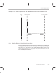
Example 7–14. Incorrect Use of Interlocked Instructions
Pipeline Operation
PC Fetch
Decode Read Execute
n STFI R1, *AR1
n+1 LDFI *AR1, R2 STFI R1, *AR1
n+2 LDFI *AR1, R2 STFI R1, *AR1
n+3 LDFI *AR1, R2 STFI R1, *AR1
n+4 LDFI *AR1, R2