
Computer Hardware User's Guide

Interlocked Operations
7-16
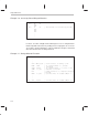
Example 7–8 shows the implementation of a busy-waiting loop. If location
LOCK is the interlock for a critical section of code, and a nonzero means the
lock is busy, the algorithm for a busy-waiting loop can be used as shown.
Example 7–8. Busy-Waiting Loop
LDI 1,R0 ; Put 1 into R0
L1: LDII @LOCK,R1 ; Interlocked operation begun
; Contents of LOCK
→ R1
STII R0,@LOCK ; Put R0 (= 1) into LOCK, XF0 = 1
; Interlocked operation ended
BNZ L1 ; Keep trying until LOCK = 0
Example 7–9 shows how a location COUNT may contain a
count
of the number
of times a particular operation must be performed. This operation may be per-
formed by any processor in the system. If the
count
is 0, the processor waits
until it is nonzero before beginning processing. The example also shows the
algorithm for modifying COUNT correctly.
Example 7–9. Multiprocessor Counter Manipulation
CT: OR 4,IOF ; XF0 = 1
; Interlocked operation ended
LDII @COUNT,R1 ; Interlocked operation begun
; Contents of COUNT → R1
BZ CT ; If COUNT = 0, keep trying
SUBI 1,R1 ; Decrement R1 (= COUNT)
STII R1,@COUNT ; Update COUNT, XF0 = 1
; Interlocked operation ended
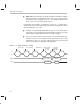
Figure 7–2 illustrates multiple ’C3x devices sharing global memory and using the
interlocked instructions as in Example 7–10, Example 7–11, and Example 7–12.