
Computer Hardware User's Guide

Repeat Modes
7-6
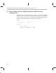
The RPTS instruction loads all registers and mode bits necessary for the opera-
tion of the single-instruction repeat mode. Step 1 loads the start address of the
block into RS. Step 2 loads the end address into the RE (end address of the
block). Since this is a repeat of a single instruction, the start address and the end
address are the same. Step 3 sets the status register to indicate the repeat
mode of operation. Step 4 indicates that this is the repeat single-instruction
mode of operation. Step 5 loads
src
into RC.
7.1.5 Repeat-Mode Restrictions
Because the block-repeat modes modify the program counter, no other
instruction can modify the program counter at the same time. Two rules apply:
Rule 1: The last instruction in the block (or the only instruction in a block of
size 1) cannot be a B
cond
, BR, DB
cond
, CALL, CALL
cond
, TRAP-
cond
, RETI
cond
, RETS
cond
, IDLE, RPTB, or RPTS. Example 7–3
shows an incorrectly placed standard branch.
Rule 2: None of the last four instructions from the bottom of the block (or the
only instruction in a block of size 1) can be a B
cond
D, BRD, or
DB
cond
D. Example 7–4 shows an incorrectly placed delayed
branch.
If either of these rules is violated, the PC is undefined.
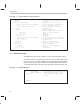
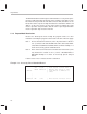
Example 7–3. Incorrectly Placed Standard Branch
LDI 15,RC ; Load repeat counter with 15
RPTB ENDLOOP ; Execute the block of code
STLOOP ; from STLOOP to ENDLOOP 16
; times
.
.
.
ENDLOOP BR OOPS ; This branch violates rule 1