TMS320C3x User’s Guide Literature Number: SPRU031E 2558539-9761 revision L July 1997 Printed on Recycled Paper
IMPORTANT NOTICE Texas Instruments (TI) reserves the right to make changes to its products or to discontinue any semiconductor product or service without notice, and advises its customers to obtain the latest version of relevant information to verify, before placing orders, that the information being relied on is current. TI warrants performance of its semiconductor products and related software to the specifications applicable at the time of sale in accordance with TI’s standard warranty.
Preface Read This First About This Manual This user’s guide serves as an applications reference book for the TMS320C3x generation of digital signal processors (DSPs). These include the TMS320C30, TMS320C31, TMS320LC31, and TMS320C32. Throughout the book, all references to ’C3x refer collectively to the ’C30, ’C31, ’LC31 and ’C32. This book provides information to assist managers and hardware/software engineers in application development.
Notational Conventions - In syntax descriptions, the instruction, command, or directive is in bold typeface and parameters are in an italic typeface. Portions of a syntax that are in bold must be entered as shown; portions of a syntax that are in italics describe the type of information that must be entered. Here is an example of a directive syntax: .asect ”section name”, address The directive .asect has two parameters, indicated by section name and address. When you use .
Information About Cautions / Related Documentation from Texas Instruments Information About Cautions This book contains cautions. This is an example of a caution statement. A caution statement describes a situation that could potentially damage your software or equipment. The information in a caution is provided for your protection. Please read each caution carefully. Related Documentation From Texas Instruments The following books describe the TMS320 floating-point devices and related support tools.
Related Documentation from Texas Instruments / References TMS320C3x C Source Debugger User’s Guide (literature number SPRU053) tells you how to invoke the ’C3x emulator, evaluation module, and simulator versions of the C source debugger interface. This book discusses various aspects of the debugger interface, including window management, command entry, code execution, data management, and breakpoints. It also includes a tutorial that introduces basic debugger functionality.
References Digital Signal Processing Applications with the TMS320 Family, Vol. III. Texas Instruments, 1990; Prentice-Hall, Inc., 1990. Gold, Bernard, and Rader, C.M., Digital Processing of Signals. New York, NY: McGraw-Hill Company, Inc., 1969. Hamming, R.W., Digital Filters. Englewood Cliffs, NJ: Prentice-Hall, Inc., 1977. Hutchins, B., and Parks, T., A Digital Signal Processing Laboratory Using the TMS320C25. Englewood Cliffs, NJ: Prentice-Hall, Inc., 1990.
References Parsons, Thomas., Voice and Speech Processing. New York, NY: McGraw Hill Company, Inc., 1987. Rabiner, Lawrence R., and Schafer, R.W., Digital Processing of Speech Signals. Englewood Cliffs, NJ: Prentice-Hall, Inc., 1978. Shaughnessy, Douglas., Speech Communication. Reading, MA: AddisonWesley, 1987. - Image Processing Andrews, H.C., and Hunt, B.R., Digital Image Restoration. Englewood Cliffs, NJ: Prentice-Hall, Inc., 1977. Gonzales, Rafael C., and Wintz, Paul, Digital Image Processing.
References - Array Signal Processing Haykin, S., Justice, J.H., Owsley, N.L., Yen, J.L., and Kak, A.C. Array Signal Processing. Englewood Cliffs, NJ: Prentice-Hall, Inc., 1985. Hudson, J.E. Adaptive Array Principles. New York, NY: John Wiley and Sons, 1981. Monzingo, R.A., and Miller, J.W. Introduction to Adaptive Arrays. New York, NY: John Wiley and Sons, 1980.
If You Need Assistance If You Need Assistance . . . - World-Wide Web Sites TI Online Semiconductor Product Information Center (PIC) DSP Solutions 320 Hotline On-line Microcontroller Home Page Networking Home Page t - - - - http://www.ti.com http://www.ti.com/sc/docs/pic/home.htm http://www.ti.com/dsps http://www.ti.com/sc/docs/dsps/support.htm http://www.ti.com/sc/micro http://www.ti.com/sc/docs/network/nbuhomex.
If You Need Assistance / Trademarks - Documentation When making suggestions or reporting errors in documentation, please include the following information that is on the title page: the full title of the book, the publication date, and the literature number. Mail: Texas Instruments Incorporated Email: comments@books.sc.ti.com Technical Documentation Services, MS 702 P.O.
Contents Contents 1 Introduction . . . . . . . . . . . . . . . . . . . . . . . . . . . . . . . . . . . . . . . . . . . . . . . . . . . . . . . . . . . . . . . . . . . . . 1-1 A general description of the TMS320C30, TMS320C31, and TMS320C32, their key features, and typical applications. 1.1 1.2 2 TMS320C3x Devices . . . . . . . . . . . . . . . . . . . . . . . . . . . . . . . . . . . . . . . . . . . . . . . . . . . . . . . . 1.1.1 TMS320C3x Key Specifications . . . . . . . . . . . . . . . . . . . . . . .
Contents 3 CPU Registers . . . . . . . . . . . . . . . . . . . . . . . . . . . . . . . . . . . . . . . . . . . . . . . . . . . . . . . . . . . . . . . . . . . 3-1 Description of the registers in the CPU register file. 3.1 3.2 3.3 4 Memory and the Instruction Cache . . . . . . . . . . . . . . . . . . . . . . . . . . . . . . . . . . . . . . . . . . . . . . . . 4-1 Description of memory maps with explanation of instruction cache architecture, algorithm, and control bits. 4.1 4.2 4.3 5 Memory . . . . .
Contents 5.3.3 5.3.4 5.3.5 5.4 5.5 5.6 5.7 5.8 5.9 5.10 5.11 6 Addressing Modes . . . . . . . . . . . . . . . . . . . . . . . . . . . . . . . . . . . . . . . . . . . . . . . . . . . . . . . . . . . . . . 6-1 Operation, encoding, and implementation of addressing modes; format descriptions; system stack management. 6.1 6.2 6.3 6.4 6.5 6.6 6.7 6.8 6.9 6.10 7 Single-Precision Floating-Point Format . . . . . . . . . . . . . . . . . . . . . . . . . . . . . . . . .
Contents 7.2 7.3 7.4 7.5 7.6 7.7 7.8 7.9 8 Pipeline Operation . . . . . . . . . . . . . . . . . . . . . . . . . . . . . . . . . . . . . . . . . . . . . . . . . . . . . . . . . . . . . . . 8-1 Discussion of the pipeline of operations on the TMS320C3x 8.1 8.2 8.3 8.4 8.5 xvi 7.1.4 RPTS Instruction . . . . . . . . . . . . . . . . . . . . . . . . . . . . . . . . . . . . . . . . . . . . . . . . . . . . 7-5 7.1.5 Repeat-Mode Restrictions . . . . . . . . . . . . . . . . . . . . . . . . . . . . . . . . .
Contents 9 TMS320C30 and TMS320C31 External-Memory Interface . . . . . . . . . . . . . . . . . . . . . . . . . . . . 9-1 Description of primary and expansion interfaces for the ’C30 and ’C31; external interface timing diagrams; programmable wait-states and bank switching. 9.1 9.2 9.3 9.4 9.5 9.6 Overview . . . . . . . . . . . . . . . . . . . . . . . . . . . . . . . . . . . . . . . . . . . . . . . . . . . . . . . . . . . . . . . . . . 9-2 Memory Interface Signals . . . . . . . . . . . . . . . . . . . .
Contents 11.2 11.1.3 TMS320C31 Boot-Loading Sequence . . . . . . . . . . . . . . . . . . . . . . . . . . . . . . . . 11-4 11.1.4 TMS320C31 Boot Data Stream Structure . . . . . . . . . . . . . . . . . . . . . . . . . . . . . 11-7 11.1.5 Interrupt and Trap-Vector Mapping . . . . . . . . . . . . . . . . . . . . . . . . . . . . . . . . . 11-11 11.1.6 TMS320C31 Boot-Loader Precautions . . . . . . . . . . . . . . . . . . . . . . . . . . . . . . 11-13 TMS320C32 Boot Loader . . . . . . . . . . . . . . . . . . . .
Contents 12.3.5 12.3.6 12.3.7 12.3.8 12.3.9 12.3.10 12.3.11 TMS320C32 DMA Internal Priority Schemes . . . . . . . . . . . . . . . . . . . . . . . . . CPU and DMA Controller Arbitration . . . . . . . . . . . . . . . . . . . . . . . . . . . . . . . . DMA and Interrupts . . . . . . . . . . . . . . . . . . . . . . . . . . . . . . . . . . . . . . . . . . . . . . . DMA Memory Transfer Timing . . . . . . . . . . . . . . . . . . . . . . . . . . . . . . . . . . . . . DMA Initialization/Reconfiguration . . . . . .
Figures Figures 1–1 2–1 2–2 2–3 2–4 2–5 2–6 2–7 2–8 2–9 2–10 3–1 3–2 3–3 3–4 3–5 3–6 3–7 3–8 3–9 3–10 3–11 3–12 4–1 4–2 4–3 4–4 4–5 4–6 4–7 4–8 4–9 4–10 4–11 4–12 xx TMS320C3x Devices Block Diagram . . . . . . . . . . . . . . . . . . . . . . . . . . . . . . . . . . . . . . . . . . . . 1-3 TMS320C30 Block Diagram . . . . . . . . . . . . . . . . . . . . . . . . . . . . . . . . . . . . . . . . . . . . . . . . . . . . 2-3 TMS320C31 Block Diagram . . . . . . . . . . . . . . . . . . . . . . . . . . . . . . . .
Figures 5–1 5–2 5–3 5–4 5–5 5–6 5–7 5–8 5–9 5–10 5–11 5–12 5–13 5–14 5–15 5–16 5–17 5–18 5–19 5–20 5–21 5–22 5–23 6–1 6–2 6–3 6–4 6–5 6–6 6–7 6–8 6–9 6–10 6–11 7–1 7–2 7–3 7–4 7–5 7–6 7–7 Short-Integer Format and Sign-Extension of Short Integers . . . . . . . . . . . . . . . . . . . . . . . . . 5-2 Single-Precision Integer Format . . . . . . . . . . . . . . . . . . . . . . . . . . . . . . . . . . . . . . . . . . . . . . . . . 5-2 Short Unsigned-Integer Format and Zero Fill . . . . . . . . . . . . . . . .
Figures 7–8 7–9 7–10 7–11 7–12 7–13 7–14 8–1 8–2 8–3 8–4 8–5 8–6 8–7 9–1 9–2 9–3 9–4 9–5 9–6 9–7 9–8 9–9 9–10 9–11 9–12 9–13 9–14 9–15 9–16 9–17 9–18 9–19 9–20 9–21 9–22 9–23 9–24 9–25 9–26 10–1 10–2 10–3 10–4 xxii DMA Interrupt Processing . . . . . . . . . . . . . . . . . . . . . . . . . . . . . . . . . . . . . . . . . . . . . . . . . . . . . 7-39 Parallel CPU and DMA Interrupt Processing . . . . . . . . . . . . . . . . . . . . . . . . . . . . . . . . . . . . . 7-40 Flow of Traps . . . . . . . . . . . .
Figures 10–5 10–6 10–7 10–8 10–9 10–10 10–11 10–12 10–13 10–14 10–15 10–16 10–17 10–18 10–19 10–20 10–21 10–22 10–23 10–24 10–25 10–26 10–27 10–28 10–29 10–30 10–31 10–32 10–33 10–34 10–35 10–36 10–37 10–38 10–39 10–40 10–41 10–42 11–1 11–2 11–3 11–4 STRB1 Control Register . . . . . . . . . . . . . . . . . . . . . . . . . . . . . . . . . . . . . . . . . . . . . . . . . . . . . . 10-8 IOSTRB Control Register . . . . . . . . . . . . . . . . . . . . . . . . . . . . . . . . . . . . . . . . . . . . . . . . . .
Figures 11–5 11–6 11–7 11–8 12–1 12–2 12–3 12–4 12–5 12–6 12–7 12–8 12–9 12–10 12–11 12–12 12–13 12–14 12–15 12–16 12–17 12–18 12–19 12–20 12–21 12–22 12–23 12–24 12–25 12–26 12–27 12–28 12–29 12–30 12–31 12–32 12–33 12–34 12–35 12–36 12–37 12–38 12–39 12–40 xxiv Boot-Loader Serial-Port Load Flowchart . . . . . . . . . . . . . . . . . . . . . . . . . . . . . . . . . . . . . . . . 11-18 Boot-Loader Memory-Load Flowchart . . . . . . . . . . . . . . . . . . . . . . . . . . . . . . . . . . . . . . . . . .
Figures 12–41 12–42 12–43 12–44 12–45 12–46 12–47 12–48 12–49 13–1 13–2 13–3 13–4 13–5 13–6 C–1 TMS320C30 and TMS320C31 CPU/DMA Interrupt-Enable Register . . . . . . . . . . . . . . . 12-60 TMS320C32 CPU/DMA Interrupt-Enable Register . . . . . . . . . . . . . . . . . . . . . . . . . . . . . . . 12-60 Mechanism for No DMA Synchronization . . . . . . . . . . . . . . . . . . . . . . . . . . . . . . . . . . . . . . . 12-65 Mechanism for DMA Source Synchronization . . . . . . . . . . . . . . . . . . . . . . .
Tables Tables 1–1 1–2 2–1 2–2 3–1 3–2 3–3 3–4 3–5 4–1 5–1 5–2 5–3 6–1 6–2 6–3 7–1 7–2 7–3 7–4 7–5 7–6 7–7 7–8 7–9 7–10 8–1 8–2 9–1 9–2 9–3 9–4 9–5 9–6 10–1 xxvi TMS320C30, TMS320C31, TMS320LC31, and TMS320C32 Comparison . . . . . . . . . . . . 1-5 Typical Applications of the TMS320 Family . . . . . . . . . . . . . . . . . . . . . . . . . . . . . . . . . . . . . . . 1-7 Primary CPU Registers . . . . . . . . . . . . . . . . . . . . . . . . . . . . . . . . . . . . . . . . . . . . . . . . . . . . . . . .
Tables 10–2 10–3 10–4 10–5 10–6 10–7 10–8 10–9 10–10 10–11 10–12 10–13 10–14 10–15 10–16 11–1 11–2 11–3 11–4 11–5 11–6 11–7 11–8 12–1 12–2 12–3 12–4 12–5 12–6 12–7 12–8 13–1 13–2 13–3 13–4 13–5 13–6 13–7 13–8 13–9 13–10 13–11 13–12 13–13 13–14 A–1 Data-Access Sequence for a Memory Configuration with Two Banks . . . . . . . . . . . . . . . 10-14 Wait-State Generation . . . . . . . . . . . . . . . . . . . . . . . . . . . . . . . . . . . . . . . . . . . . . . . . . . . . . . . 10-16 BNKCMP and Bank Size . .
Examples Examples 4–1 5–1 5–2 5–3 5–4 5–5 5–6 5–7 5–8 5–9 5–10 5–11 5–12 5–13 5–14 5–15 5–16 5–17 6–1 6–2 6–3 6–4 6–5 6–6 6–7 6–8 6–9 6–10 6–11 6–12 6–13 6–14 6–15 6–16 6–17 6–18 xxviii Pipeline Effects of Modifying the Cache Control Bits . . . . . . . . . . . . . . . . . . . . . . . . . . . . . . 4-23 Positive Number . . . . . . . . . . . . . . . . . . . . . . . . . . . . . . . . . . . . . . . . . . . . . . . . . . . . . . . . . . . . . 5-10 Negative Number . . . . . . . . . . . . . . . . . . . . . . . .
Examples 6–19 6–20 6–21 6–22 6–23 6–24 6–25 6–26 7–1 7–2 7–3 7–4 7–5 7–6 7–7 7–8 7–9 7–10 7–11 7–12 7–13 7–14 7–15 8–1 8–2 8–3 8–4 8–5 8–6 8–7 8–8 8–9 8–10 8–11 8–12 8–13 8–14 8–15 8–16 8–17 8–18 12–1 12–2 Indirect Addressing With Postindex Add and Bit-Reversed Modify . . . . . . . . . . . . . . . . . . 6-17 Short-Immediate Addressing . . . . . . . . . . . . . . . . . . . . . . . . . . . . . . . . . . . . . . . . . . . . . . . . . . 6-18 Long-Immediate Addressing . . . . . . . . . . . . . . . . . . . . .
Examples 12–3 12–4 12–5 12–6 12–7 12–8 12–9 12–10 xxx Serial-Port Register Setup #1 . . . . . . . . . . . . . . . . . . . . . . . . . . . . . . . . . . . . . . . . . . . . . . . . . Serial-Port Register Setup #1 . . . . . . . . . . . . . . . . . . . . . . . . . . . . . . . . . . . . . . . . . . . . . . . . . Serial-Port Register Setup #2 . . . . . . . . . . . . . . . . . . . . . . . . . . . . . . . . . . . . . . . . . . . . . . . . . CPU Transfer With Serial Port Transmit Polling Method . . . . . . . . .
Chapter 1 Introduction The TMS320C3x generation of digital signal processors (DSPs) are highperformance CMOS 32-bit floating-point devices in the TMS320 family of single-chip DSPs. The ’C3x generation integrates both system control and math-intensive functions on a single controller. This system integration allows fast, easy data movement and high-speed numeric processing performance.
TMS320C3x Devices 1.1 TMS320C3x Devices The ’C3x family consists of three members: the ’C30, ’C31, and ’C32. The ’C30, ’C31, and ’C32 can perform parallel multiply and arithmetic logic unit (ALU) operations on integer or floating-point data in a single cycle.
TMS320C3x Devices Figure 1–1. TMS320C3x Devices Block Diagram Program cache (64 x 32) Expansion port (’C30) memory interface IOSTRB 32-bit data access XRDY XD31-0 XA12-0 32-bit program access 1.1.
TMS320C3x Devices 1.1.4 TMS320C32 The ’C32 is the newest member of the ’C3x generation. They are enhanced versions of the ’C3x family and the lowest cost floating-point processors on the market today. These enhancements include a variable-width memory interface, two-channel DMA coprocessor with configurable priorities, flexible boot loader, and a relocatable interrupt vector table.
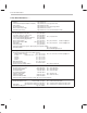
Table 1–1.
Memory (words) On-Chip Device Name ’C32 Off-Chip Freq (MHz) Cycle Time (ns) RAM ROM Cache 40 50 512 Boot loader 64 16M 50 40 512 Boot loader 64 60 33 512 Boot loader 64 Peripherals Serial DMA Channels Timers Package Type 32/16/8 1 2 2 144 PQFP 0° to 85° (commercial) –40° to 125° (extended) 16M 32/16/8 1 2 2 144 PQFP 0° to 85° (commercial) –40° to 125° (extended) –55° to 125° (military) 16M 32/16/8 1 2 2 144 PQFP 0° to 85° (commercial) Parallel (5 V) Tempera
Typical Applications 1.2 Typical Applications The TMS320 family’s versatility, realtime performance, and multiple functions offer flexible design approaches in a variety of applications, which are shown in Table 1–2. Table 1–2.
Chapter 2 Architectural Overview This chapter provides an architectural overview of the ’C3x processor. It includes a discussion of the CPU, memory interface, boot loader, peripherals, and direct memory access (DMA) of the ’C3x processor. Topic Page 2.1 Overview . . . . . . . . . . . . . . . . . . . . . . . . . . . . . . . . . . . . . . . . . . . . . . . . . . . . . 2-2 2.2 Central Processing Unit (CPU) . . . . . . . . . . . . . . . . . . . . . . . . . . . . . . . . . 2-6 2.
Overview 2.1 Overview The ’C3x architecture responds to system demands that are based on sophisticated arithmetic algorithms that emphasize both hardware and software solutions. High performance is achieved through the precision and wide dynamic range of the floating-point units, large on-chip memory, a high degree of parallelism, and the DMA controller. Figure 2–1 through Figure 2–3 show functional block diagrams of the ’C30, ’C31, and ’C32 architectures, respectively.
Overview Figure 2–1.
Overview ÉÉÉÉ ÉÉÉ ÉÉÉÉ ÉÉÉ ÉÉÉÉ ÉÉÉÉ Figure 2–2.
Overview Figure 2–3. TMS320C32 Block Diagram RAM block 0 (256 × 32) Program cache (64 × 32) 24 32 24 RAM block 1 (256 × 32) 32 24 32 ÉÉÉ ÉÉÉ Boot ROM 24 32 32 PC 24 PADDR bus Multiplexer DDATA bus DADDR1 bus DADDR2 bus External memory interface DMADATA bus Controller DMAADDR bus Multiplexer DMA controller STRB0 control reg.
Central Processing Unit (CPU) 2.2 Central Processing Unit (CPU) The ’C3x devices (’C30, ’C31, and ’C32) have a register-based CPU architecture. The CPU consists of the following components: - Floating-point/integer multiplier Arithmetic logic unit (ALU) 32-bit barrel shifter Internal buses (CPU1/CPU2 and REG1/REG2) Auxiliary register arithmetic units (ARAUs) CPU register file Figure 2–4 shows a diagram of the various CPU components.
Central Processing Unit (CPU) Figure 2–4.
Central Processing Unit (CPU) 2.2.1 Floating-Point/Integer Multiplier The multiplier performs single-cycle multiplications on 24-bit integer and 32-bit floating-point values. The ’C3x implementation of floating-point arithmetic allows for floating-point or fixed-point operations at speeds up to 33-ns per instruction cycle. To gain even higher throughput, you can use parallel instructions to perform a multiply and an ALU operation in a single cycle.
CPU Primary Register File 2.3 CPU Primary Register File The ’C3x provides 28 registers in a multiport register file that is tightly coupled to the CPU. Table 2–1 lists the register names and functions. All of the primary registers can be operated upon by the multiplier and ALU and can be used as general-purpose registers. The registers also have some special functions. For example, the eight extended-precision registers are especially suited for maintaining extended-precision floating-point results.
CPU Primary Register File Table 2–1. Primary CPU Registers (Continued) Register Name Assigned Function IR1 Section Page Index register 1 3.1.4 3-4 BK Block-size register 3.1.5 3-4 SP System-stack pointer 3.1.6 3-4 ST Status register 3.1.7 3-5 IE CPU/DMA interrupt-enable register 3.1.8 3-9 IF CPU interrupt flag 3.1.9 3-11 IOF I/O flag 3.1.10 3-16 RS Repeat start-address 3.1.11 3-17 RE Repeat end-address 3.1.11 3-17 RC Repeat counter 3.1.
CPU Primary Register File The ARAU uses the 32-bit block size register (BK) in circular addressing to specify the data block size. The system-stack pointer (SP) is a 32-bit register that contains the address of the top of the system stack. The SP always points to the last element pushed onto the stack. A push performs a preincrement; a pop performs a postdecrement of the system-stack pointer. The SP is manipulated by interrupts, traps, calls, returns, and the PUSH and POP instructions. See Section 6.
Other Registers 2.4 Other Registers The program-counter (PC) is a 32-bit register containing the address of the next instruction to fetch. Although the PC is not part of the CPU register file, it is a register that can be modified by instructions that modify the program flow. The instruction register (IR) is a 32-bit register that holds the instruction opcode during the decode phase of the instruction. This register is used by the instruction decode control circuitry and is not accessible to the CPU.
Memory Organization 2.5 Memory Organization The total memory space of the ’C3x is 16M (million) 32-bit words. Program, data, and I/O space are contained within this 16M-word address space, allowing the storage of tables, coefficients, program code, or data in either RAM or ROM. In this way, memory usage is maximized and memory space allocated as desired. 2.5.1 RAM, ROM, and Cache Figure 2–5 shows how the memory is organized on the ’C30. RAM blocks 0 and 1 are each 1K 32 bits.
Memory Organization ÉÉÉÉÉ ÉÉÉÉÉ ÉÉÉÉÉ ÉÉÉÉÉ ÉÉÉÉÉ ÉÉÉÉÉ Figure 2–5.
Memory Organization Figure 2–6.
Memory Organization Figure 2–7.
Memory Organization 2.5.2 Memory Addressing Modes The ’C3x supports a base set of general-purpose instructions as well as arithmeticintensive instructions that are particularly suited for digital signal processing and other numeric-intensive applications. See Chapter 6, Addressing Modes, for more information. Four groups of addressing modes are provided on the ’C3x. Each group uses two or more of several different addressing types. The following list shows the addressing modes with their addressing types.
Internal Bus Operation 2.6 Internal Bus Operation Much of the ’C3x’s high performance is due to internal busing and parallelism. Separate buses allow for parallel program fetches, data accesses, and DMA accesses: - Program buses: PADDR and PDATA Data buses: DADDR1, DADDR2, and DDATA DMA buses: DMAADDR and DMADATA These buses connect all of the physical spaces (on-chip memory, off-chip memory, and on-chip peripherals) supported by the ’C3x.
External Memory Interface 2.7 External Memory Interface The ’C30 provides two external interfaces: the primary bus and the expansion bus. The ’C31 provides one external interface: the primary bus. The ’C32 provides one enhanced external interface with three independent multi-function strobes. These buses consist of a 32-bit data bus and a set of control signals. The primary and enhanced memory buses have a 24-bit address bus, whereas the expansion bus has a 13-bit address bus.
External Memory Interface 2.7.2 TMS320C32 8-, 16-, and 32-Bit Data Memory The ’C32 external memory interface can load and store 8-, 16-, or 32-bit quantities into external memory and convert them into an internally-equivalent 32-bit representation. The external memory interface accomplishes this without changing the CPU instruction set. Figure 2–8 shows the supported external memory widths, data types and sizes for zero wait-state memory and the associated cycle count.
Interrupts 2.8 Interrupts The ’C3x supports four external interrupts (INT3–INT0), a number of internal interrupts, and a nonmaskable external RESET signal. These can be used to interrupt either the DMA or the CPU. When the CPU responds to the interrupt, the IACK pin can be used to signal an external interrupt acknowledge. Section 7.5, Reset Operation, on page 7-21 covers RESET and interrupt processing. The ’C30 and ’C31 external interrupts are level-triggered.
Peripherals 2.9 Peripherals All ’C3x peripherals are controlled through memory-mapped registers on a dedicated peripheral bus. This peripheral bus is composed of a 32-bit data bus and a 24-bit address bus. This peripheral bus permits straightforward communication to the peripherals. The ’C3x peripherals include two timers and two serial ports (only one serial port and one DMA coprocessor are available on the ’C31 and one serial port and two DMA coprocessor channels on the ’C32).
Peripherals 2.9.1 Timers The two timer modules are general-purpose 32-bit timer/event counters with two signaling modes and internal or external clocking. They can signal internally to the ’C3x or externally to the outside world at specified intervals or they can count external events. Each timer has an I/O pin that can be used as an input clock to the timer, as an output signal driven by the timer, or as a general-purpose I/O pin. See Chapter 12, Peripherals, for more information about timers. 2.9.
Direct Memory Access (DMA) 2.10 Direct Memory Access (DMA) The on-chip DMA controller can read from or write to any location in the memory map without interfering with the CPU operation. The ’C3x can interface to slow, external memories and peripherals without reducing throughput to the CPU. The DMA controller contains its own address generators, source and destination registers, and transfer counter. Dedicated DMA address and data buses minimize conflicts between the CPU and the DMA controller.
Direct Memory Access (DMA) Figure 2–10.
TMS320C30, TMS320C31, and TMS320C32 Differences 2.11 TMS320C30, TMS320C31, and TMS320C32 Differences Table 2–2 shows the major differences between the ’C32, ’C31, and the ’C30 devices.
TMS320C30, TMS320C31, and TMS320C32 Differences Table 2–2.
Chapter 3 CPU Registers The central processing unit (CPU) register file contains 28 registers that can be operated on by the multiplier and arithmetic logic unit (ALU). Included in the register file are the auxiliary registers, extended-precision registers, and index registers. Three registers in the ’C32 CPU register file have been modified to support new features (2-channel DMAs, program execution from 16-bit memory width, etc.
CPU Multiport Register File 3.1 CPU Multiport Register File The ’C3x provides 28 registers in a multiport register file that is tightly coupled to the CPU. The program counter (PC) is not included in the 28 registers. All of these registers can be operated on by the multiplier and the ALU and can be used as general-purpose 32-bit registers. Table 3–1 lists the registers’ names and assigned functions of the ’C3x. Table 3–1.
CPU Multiport Register File The registers also have some special functions for which they are particularly appropriate. For example, the eight extended-precision registers are especially suited for maintaining extended-precision floating-point results. The eight auxiliary registers support a variety of indirect addressing modes and can be used as general-purpose 32-bit integer and logical registers.
CPU Multiport Register File 3.1.2 Auxiliary Registers (AR7–AR0) The CPU can access the eight 32-bit auxiliary registers (AR7–AR0), and the two auxiliary register arithmetic units (ARAUs) can modify them. The primary function of the auxiliary registers is the generation of 24-bit addresses. However, they can also operate as loop counters in indirect addressing or as 32-bit generalpurpose registers that can be modified by the multiplier and ALU. See Chapter 6, Addressing Modes, for more information. 3.1.
CPU Multiport Register File 3.1.7 Status (ST) Register The status (ST) register contains global information about the state of the CPU. Operations usually set the condition flags of the status register according to whether the result is 0, negative, etc. This includes register load and store operations as well as arithmetic and logical functions.
CPU Multiport Register File Table 3–2.
CPU Multiport Register File Table 3–2. Status Register Bits (Continued) Bit Name CF Reset Value 0 Name Description Cache freeze Enables or disables the instruction cache Set CF = 1 to freeze the cache (cache is not updated), including LRU stack manipulation. If the cache is enabled (CE = 1), fetches from the cache are allowed, but modification of the cache contents is not allowed. Cache clearing (CC = 1) is allowed. At reset, this bit is cleared to 0, but it is set to 1 after reset.
CPU Multiport Register File Table 3–2. Status Register Bits (Continued) Bit Name Reset Value Name Description PRGW Dependent on PRGW pin level Program width status (‘C32 only) Indicates the status of the external input PRGW pin. When the signal of the PRGW pin is high, the PRGW status bit is set to 1, indicating a 16-bit memory width. The ‘C32 performs two fetches to retrieve a single 32-bit instruction word.
CPU Multiport Register File 3.1.8 CPU/DMA Interrupt-Enable (IE) Register The CPU/DMA interrupt-enable (IE) register of the ’C30, ’C31, and ’C32 are 32-bit registers (see Figure 3–5 and Figure 3–6). The CPU interrupt-enable bits are in locations 10–0 for ’C30 and ’C31 devices, and 11–0 for ’C32 devices. The direct memory access (DMA) interrupt-enable bits are in locations 26–16 for ‘C30 and ‘C31 devices, and 31–16 for ’C32 devices. A 1 in a CPU/DMA IE bit enables the corresponding interrupt.
CPU Multiport Register File Table 3–3.
CPU Multiport Register File Table 3–3. IE Bits and Functions(Continued) Abbreviation 3.1.
CPU Multiport Register File Figure 3–7. TMS320C30 CPU Interrupt Flag (IF) Register 31–16 15–12 11 10 9 xx yy yy DINT TINT1 R/W R/W R/W Notes: 8 7 6 5 TINT0 RINT1 XINT1 RINT0 R/W R/W R/W R/W 4 3 2 1 0 XINT0 INT3 INT2 INT1 INT0 R/W R/W R/W R/W R/W 1) xx = reserved bit, read as 0 2) yy = reserved bit, set to 0 at reset; can store value 3) R = read, W = write Figure 3–8.
CPU Multiport Register File Table 3–4.
CPU Multiport Register File 3.1.9.1 Interrupt-Trap Table Pointer (ITTP) Similar to the rest of the ‘C3x device family, the ’C32’s reset vector location remains at address 0. However, the interrupt and trap vectors are relocatable. This is achieved by the interrupt-trap table pointer (ITTP) bit field in the CPU interrupt flag register, shown in Figure 3–9. The ITTP bit field dictates the starting location (base) of the interrupt-trap vector table.
CPU Multiport Register File Figure 3–11.Interrupt and Trap Vector Locations EA (ITTP) + 00h Reserved EA (ITTP) + 01h INT0 EA (ITTP) + 02h INT1 EA (ITTP) + 03h INT2 EA (ITTP) + 04h INT3 EA (ITTP) + 05h XINT0 EA (ITTP) + 06h RINT0 EA (ITTP) + 07h Reserved EA (ITTP) + 08h Reserved EA (ITTP) + 09h TINT0 EA (ITTP) + 0Ah TINT1 EA (ITTP) + 0Bh DINT0 EA (ITTP) + 0Ch DINT1 EA (ITTP) + 0Dh Reserved EA (ITTP) + 1Fh EA (ITTP) + 20h TRAP0 . . . .
CPU Multiport Register File 3.1.10 I/O Flag (IOF) Register The I/O flag (IOF) register is shown in Figure 3–12 and controls the function of the dedicated external pins, XF0 and XF1. These pins can be configured for input or output. The pins can also be read from and written to. At reset, 0 is written to this register. Table 3–5 describes the I/O flags register bits, their names, and their functions. Figure 3–12.
CPU Multiport Register File 3.1.11 Repeat-Counter (RC) and Block-Repeat (RS, RE) Registers The repeat-counter (RC) register is a 32-bit register that specifies the number of times a block of code is to be repeated when a block repeat is performed. If RC contains the number n, the loop is executed n + 1 times. The 32-bit repeat start-address (RS) register contains the starting address of the program-memory block to be repeated when the CPU is operating in the repeat mode.
Other Registers 3.2 Other Registers 3.2.1 Program-Counter (PC) Register The program counter (PC) is a 32-bit register containing the address of the next instruction fetch. While the program-counter register is not part of the CPU register file, it can be modified by instructions that modify the program flow. 3.2.2 Instruction Register (IR) The instruction register (IR) is a 32-bit register that holds the instruction opcode during the decode phase of the instruction.
Reserved Bits and Compatibility 3.3 Reserved Bits and Compatibility To retain compatibility with future members of the ’C3x family of microprocessors, reserved bits that are read as 0 must be written as 0. You must not modify the current value of a reserved bit that has an undefined value. In other cases, you should maintain the reserved bits as specified.
Chapter 4 Memory and the Instruction Cache The ’C3x provides a total memory space of 16M (million) 32-bit words that contain program, data, and I/O space. Two RAM blocks of 1K 32 bits each (available on the ’C30 and ’C31) or two RAM blocks of 256 32 bits (available on the ’C32) and a ROM block of 4K 32 bits (available only on the ’C30) or boot loader (available on the ’C31 and the ’C32) permit two CPU accesses in a single cycle.
Memory 4.1 Memory The ’C3x accesses a total memory space of 16M (million) 32-bit words of program, data, and I/O space and allows tables, coefficients, program code, or data to be stored in either RAM or ROM. In this way, you can maximize memory usage and allocate memory space as desired. RAM blocks 0 and 1 are each 1K 32 bits on the ’C30 and ’C31. The ROM block is 4K 32 bits on the ’C30. The ’C31 and ’C32 have a boot ROM.
Memory - Microcomputer Mode In microcomputer mode, the 4K on-chip ROM is mapped into locations 0h–0FFFh. There are 192 locations (0h–0BFh) within this block for interrupt vectors, trap vectors, and a reserved space (’C30). Locations 1000h– 7FFFFFh are accessed over the external memory port (STRB active). Section 4.1.2, Peripheral Bus Memory Map, on page 4-9 describes the peripheral memory maps in greater detail and Section 4.
Memory Figure 4–1. TMS320C30 Memory Maps 0h 03Fh 040h Reset, interrupt, trap vectors, and reserved locations (64) (external STRB active) 801FFFh 802000h Reset, interrupt, trap vectors, and reserved locations (192) 0BFh 0C0h External STRB active (8.
Memory 4.1.1.2 TMS320C31 Memory Map The memory map depends on whether the processor is running in microprocessor mode (MCBL/MP = 0) or microcomputer mode (MCBL/MP = 1). The memory maps for these modes are similar (see Figure 4–2 on page 4-6). Locations 800000h–807FFFh are reserved. All of the memory-mapped peripheral bus registers are in locations 808000h–8097FFh. In both modes, RAM block 0 is located at addresses 809800h–809BFFh, and RAM block 1 is located at addresses 809C00h–809FFFh.
Memory Figure 4–2. TMS320C31 Memory Maps 0h 03Fh 040h Reset, interrupt, trap vectors, and reserved locations (64) (external STRB active) External STRB active (8.192M words) 0h Reserved for bootloader operations† 0FFFh 1000h 400000h Boot 1 Boot 2 7FFFFFh 800000h 7FFFFFh 800000h Reserved (32K words) Reserved (32K words) 807FFFh 808000h 807FFFh 808000h 8097FFh 809800h External STRB active (8.
Memory 4.1.1.3 TMS320C32 Memory Map The memory map depends on whether the processor is running in microprocessor mode (MCBL/MP = 0) or microcomputer mode (MCBL/MP = 1). The memory maps for these modes are similar (see Figure 4–3 on page 4-8). Locations 800000h–807FFFh, 809800h–80FFFh, and 830000H–87FDFFh are reserved. Locations 810000h–82FFFFh are mapped to the external bus with IOSTRB active. All of the memory-mapped peripheral bus registers are in locations 808000h–8097FFh.
Memory Figure 4–3. TMS320C32 Memory Maps 0h 0h Reset-vector location 0FFFh 1000h External memory STRB0 active (8.192M words) External memory STRB0 active (8.
Memory 4.1.2 Peripheral Bus Memory Map The following sections describe the peripherial bus memory maps for the ’C30, ’C31, and ’C32. 4.1.2.1 TMS320C30 Peripheral Bus Memory Map The ’C30 memory-mapped peripheral registers are located starting at address 808000h. Figure 4–4 on page 4-10 shows the peripheral bus memory map. The shaded blocks are reserved.
Memory Figure 4–4.
Memory 4.1.2.2 TMS320C31 Peripheral Bus Memory Map The ’C31 memory-mapped peripheral registers are located starting at address 808000h. Figure 4–5 shows the peripheral bus memory map. The shaded blocks are reserved. Figure 4–5.
Memory 4.1.2.3 TMS320C32 Peripheral Bus Memory Map The ’C32’s memory-mapped peripheral and external-bus control registers are located starting at address 808000h, as shown in Figure 4–6 on page 4-13. The shaded blocks are reserved.
Memory Figure 4–6.
Reset/Interrupt/Trap Vector Map 4.2 Reset/Interrupt/Trap Vector Map The addresses for the reset, interrupt, and trap vectors are 00h–3Fh, as shown in Figure 4–7 and Figure 4–8. The reset vector contains the address of the reset routine.
Reset/Interrupt/Trap Vector Map Figure 4–7. Reset, Interrupt, and Trap Vector Locations for the TMS320C30 Microprocessor Mode 00h RESET 01h INT0 02h INT1 03h INT2 04h INT3 05h XINT0 06h RINT0 07h XINT1 08h RINT1 09h TINT0 0Ah TINT1 0Bh DINT 0Ch Reserved 1Fh 20h TRAP 0 D D D 3Bh TRAP 27 3Ch TRAP 28 (reserved) 3Dh TRAP 29 (reserved) 3Eh TRAP 30 (reserved) 3Fh TRAP 31 (reserved) Note: Traps 28–31 Traps 28–31 are reserved; do not use them.
Reset/Interrupt/Trap Vector Map Figure 4–8. Reset, Interrupt, and Trap Vector Locations for theTMS320C31 Microprocessor Mode 00h RESET 01h INT0 02h INT1 03h INT2 04h INT3 05h XINT0 06h RINT0 07h XINT1 (Reserved) 08h RINT1 (Reserved) 09h TINT0 0Ah TINT1 0Bh DINT 0Ch 1Fh 20h Reserved TRAP 0 • • • 3Bh TRAP 27 3Ch TRAP 28 (reserved) 3Dh TRAP 29 (reserved) 3Eh TRAP 30 (reserved) 3Fh TRAP 31 (reserved) Note: Traps 28–31 Traps 28–31 are reserved; do not use them.
Reset/Interrupt/Trap Vector Map Figure 4–9.
Reset/Interrupt/Trap Vector Map Figure 4–10. Interrupt and Trap Vector Locations for TMS320C32 EA (ITTP) + 00h Reserved EA (ITTP) + 01h INT0 EA (ITTP) + 02h INT1 EA (ITTP) + 03h INT2 EA (ITTP) + 04h INT3 EA (ITTP) + 05h XINT0 EA (ITTP) + 06h RINT0 EA (ITTP) + 07h Reserved EA (ITTP) + 08h Reserved EA (ITTP) + 09h TINT0 EA (ITTP) + 0Ah TINT1 EA (ITTP) + 0Bh DINT0 EA (ITTP) + 0Ch DINT1 EA (ITTP) + 0Dh Reserved EA (ITTP) + 1Fh EA (ITTP) + 20h TRAP0 . . . .
Instruction Cache 4.3 Instruction Cache A 64 × 32-bit instruction cache speeds instruction fetches and lowers system cost by caching program fetches from external memory. The instruction cache allows the use of slow, external memories while still achieving single-cycle access performances. This reduces the number of off-chip accesses necessary and allows code to be stored off-chip in slower, lower-cost memories.
Instruction Cache Figure 4–12. Instruction-Cache Architecture Segment start address registers P flags Segment words 0 Segment word 0 1 Segment word 1 LRU Stack MRU segment number SSA register 0 19 LRU segment number Segment 0 30 Segment word 30 31 Segment word 31 32 SSA register 1 0 Segment word 0 1 Segment word 1 Segment 1 30 Segment word 30 31 Segment word 31 The LRU stack determines which of the two segments qualifies as the least recently used after each access to the cache.
Instruction Cache 4.3.2 Instruction-Cache Algorithm When the ’C3x requests an instruction word from external memory, one of two possible actions occurs: a cache hit or a cache miss. - Cache Hit. The cache contains the requested instruction, and the following actions occur: J J - The instruction word is read from the cache.
Instruction Cache Only instructions may be fetched from the program cache. All reads and writes of data in memory bypass the cache. Program fetches from internal memory do not modify the cache and do not generate cache hits or misses. The program cache is a single-access memory block. Dummy program fetches (for example, those following a branch) are treated by the cache as valid program fetches and can generate cache misses and cache updates.
Instruction Cache Table 4–1. Combined Effect of the CE and CF Bits CE CF Effect 0 0 Cache not enabled 0 1 Cache not enabled 1 0 Cache enabled and not frozen 1 1 Cache enabled and frozen When the CE or CF bits of the CPU status register are modified, the following four instructions may or may not be fetched from the cache or external memory (see Example 4–1).
Chapter 5 Data Formats and Floating-Point Operation In the ’C3x architecture, data is organized into three fundamental types: integer, unsigned integer, and floating-point. The terms integer and signed integer are equivalent. The ’C3x supports short and single-precision formats for signed and unsigned integers. It also supports short, single-precision, and extendedprecision formats for floating-point data. Floating-point operations make fast, trouble-free, accurate, and precise computations.
Integer Formats 5.1 Integer Formats The ’C3x supports two integer formats: a 16-bit short-integer format and a 32-bit single-precision integer format. Note: When extended-precision registers are used as integer operands, only bits 31–0 are used; bits 39–32 remain unchanged. 5.1.1 Short-Integer Format The short-integer format is a 16-bit 2s-complement integer format for immediateinteger operands. For those instructions that assume integer operands, this format is sign-extended to 32 bits (see Figure 5–1).
Unsigned-Integer Formats 5.2 Unsigned-Integer Formats The ’C3x supports two unsigned-integer formats: a 16-bit short format and a 32-bit single-precision format. Note: In extended-precision registers, the unsigned-integer operands use only bits 31– 0; bits 39–32 remain unchanged. 5.2.1 Short Unsigned-Integer Format Figure 5–3 shows the16-bit, short, unsigned-integer format for immediate unsigned-integer operands.
Floating-Point Formats 5.
Floating-Point Formats The exponent field is a 2s-complement number that determines the factor of 2 by which the number is multiplied. Essentially, the exponent field shifts the binary point in the mantissa. If the exponent is positive, then the binary point is shifted to the right. If the exponent is negative, then the binary point is shifted to the left. For example, if man = 01.
Floating-Point Formats The following examples illustrate the range and precision of the short floatingpoint format: Most positive: Least positive: Least negative: Most negative: 5.3.2 x = (2 – 2 –11) × 27 = 2.5594 × 10² x = 1 × 2 –7 = 7.8125 × 10⁻³ x = (–1– 2 –11) × 2 –7 = –7.8163 × 10⁻³ x = –2 × 27 = – 2.
Floating-Point Formats The following examples illustrate the range and precision of the ‘C32 short floating-point format for external 16-bit data: Most positive: Least positive Least negative: Most negative: x = (2–2–8) 2127 = 3.3961775 1038 –127 x=1 2 = 5.8774717541 10–39 –8 –127 x = (–1–2 ) 2 = –5.9004306 10–39 127 38 x = (–2 2 ) = –3.
Floating-Point Formats You must use the following reserved values to represent 0 in the single-precision floating-point format: e = – 128 s = 0 f = 0 The following examples illustrate the range and precision of the single-precision floating-point format: 5.3.4 Most positive: x = (2 – 2 – 23) × 2127 = 3.4028234 × 1038 Least positive: x = 1 × 2 –127 = 5.8774717 × 10–39 Least negative: x = (–1–2 – 23) × 2 –127 = – 5.8774724 × 10–39 Most negative: x = – 2 × 2127 = – 3.
Floating-Point Formats The following examples illustrate the range and precision of the extendedprecision floating-point format: Most positive: Least positive: Least negative: Most negative: 5.3.5 x = (2 – 2 – 23) × 2127 = 3.4028234 × 1038 x = 1 × 2 –127 = 5.8774717541 × 1038 x = (–1–2 –31) × 2 –127 = – 5.8774717569 × 10–39 x = – 2 × 2127 = – 3.
Floating-Point Formats Rewrite the mantissa as: Mantissa 1 0 . 1 0 1 0 0 0 0 0 0 0 0 Step 3: Shift the decimal point of the mantissa according to the value of the exponent. If the exponent is positive, shift the binary point to the right by the value of the exponent. If the exponent is negative, shift the binary point to the left. For example, if e = 210 and the man = 01.110000000002, then the shifted mantissa becomes 0111.0000000002, which is equivalent to 7 in decimal.
Floating-Point Formats Example 5–2. Negative Number 0 1 C 0 0 0 0 0 0000 0001 1100 0000 0000 0000 0000 0000 Exponent = Sign = Fraction = 0000 00012 = 1 1 .100002 Value 10.12 × 21 = 1012. = –3 = Hex value Binary value Fraction Implied Sign Example 5–3. Fractional Number F B 4 0 0 0 0 0 1111 1011 0100 0000 0000 0000 0000 0000 Hex value Binary value Exponent = Sign = Fraction = 1111 10112 = –5 0 .100002 Value 01.12 × 2–5 = .
Floating-Point Formats 5.3.6 Conversion Between Floating-Point Formats Floating-point operations assume several different formats for inputs and outputs. These formats often require conversion from one floating-point format to another (for example, short floating-point format to extended-precision floatingpoint format). Format conversions occur automatically in hardware, with no overhead, as a part of the floating-point operations.
Floating-Point Formats Figure 5–12. Converting from Single-Precision Floating-Point Format to Extended-Precision Floating-Point Format 31 x 24 23 22 0 x y y y Single-precision floating-point format 39 32 31 30 8 7 0 x x y 0 0 8 7 0 y z z y y Extended-precision floating-point format The 8 LSBs of the mantissa field are filled with 0s. Figure 5–13.
Floating-Point Conversion (IEEE Std. 754) 5.4 Floating-Point Conversion (IEEE Std. 754) The ‘C3x floating-point format is not compatible with the IEEE standard 754 format. The IEEE floating-point format uses sign-magnitude notation for the mantissa, and the exponent is biased by 127. In a 32-bit word representing a floating-point number, the first bit is the sign bit. The next eight bits correspond to the exponent, which is expressed in an offset-by-127 format (the actual exponent is e –127).
Floating-Point Conversion (IEEE Std. 754) Figure 5–15. TMS320C3x Single-Precision 2s-Complement Floating-Point Format 31 24 22 0 s e Note: 23 f Same format as for the ’C4x In comparison, Figure 5–15 shows the the ‘C3x 2s-complement floating-point format. In this format, two cases can be used to define value v of a number: 1) If 2) If e = –128 e ≠ –128 then v = 0 then v = ss.
Floating-Point Conversion (IEEE Std. 754) Case 1 maps the IEEE positive NaNs and positive infinity to the single-precision 2s-complement most positive number. Overflow is also signaled to allow you to check for these special cases. Case 2 maps the IEEE negative NaNs and negative infinity to the singleprecision 2s-complement most negative number. Overflow is also signaled to allow you to check for these special cases.
Floating-Point Conversion (IEEE Std. 754) 5.4.1.1 IEEE-to-TMS320C3x Floating-Point Format Conversion Example 5–4 shows the fast conversion from IEEE to ’C3x floating-point format. It properly handles the general case when 0 < e < 255, and also handles 0s (that is, e = 0 and f = 0). The other special cases (denormalized, infinity, and NaN) are not treated and, if present, will give erroneous results.
Floating-Point Conversion (IEEE Std. 754) Example 5–4.IEEE-to-TMS320C3x Conversion (Fast Version) (Continued) * * * * NOTE: SINCE THE STACK POINTER SP IS USED, MAKE SURE TO INITIALIZE IT IN THE CALLING PROGRAM. * * CYCLES: 12 (WORST CASE) WORDS: 12 .
Floating-Point Conversion (IEEE Std. 754) Example 5–5. IEEE-to-TMS320C3x Conversion (Complete Version) * * * * * TITLE IEEE TO TMS320C3x CONVERSION (COMPLETE VERSION) * * * * * * * * FUNCTION: CONVERSION BETWEEN THE IEEE FORMAT AND THE TMS320C3x FLOATING-POINT FORMAT. THE NUMBER TO BE CONVERTED IS IN THE LOWER 32 BITS OF R0. THE RESULT IS STORED IN THE UPPER 32 BITS OF R0.
Floating-Point Conversion (IEEE Std. 754) Example 5–5.
Floating-Point Conversion (IEEE Std. 754) 5.4.2 Converting 2s-Complement TMS320C3x Floating-Point Format to IEEE Format This conversion is performed according to the following table: Table 5–2.
Floating-Point Conversion (IEEE Std. 754) 5.4.2.1 TMS320C3x-to-IEEE Floating-Point Format Conversion The vast majority of the numbers represented by the ’C3x floating-point format are covered by the general IEEE format and the representation of 0s. The only special case is e = –127 in the ’C3x format; this corresponds to a denormalized number in IEEE format. It is ignored in the fast version, while it is treated properly in the complete version.
Floating-Point Conversion (IEEE Std. 754) Example 5–6.TMS320C3x-to-IEEE Conversion (Fast Version) (Continued) * * CYCLES: 14 (WORST CASE) .
Floating-Point Conversion (IEEE Std. 754) Example 5–7. TMS320C3x-to-IEEE Conversion (Complete Version) * * * * * * * * * * * * * TITLE TMS320C3x TO IEEE CONVERSION (COMPLETE VERSION) SUBROUTINE TOIEEE1 FUNCTION: CONVERSION BETWEEN THE TMS320C3x FORMAT AND THE IEEE FLOATING-POINT FORMAT. THE NUMBER TO BE CONVERTED IS IN THE UPPER 32 BITS OF R0. THE RESULT WILL BE IN THE LOWER 32 BITS OF R0.
Floating-Point Conversion (IEEE Std. 754) Example 5–7.
Floating-Point Multiplication 5.5 Floating-Point Multiplication A floating-point number α can be written in floating-point format as in the following formula, where α(man) is the mantissa and α(exp) is the exponent: α = α(man) × 2α( exp) The product of α and b is c, defined as: c = α × b = α(man) × b(man) × 2(α( exp) + b ( exp)) thus: c(man) = α(man) × b(man) c(exp) = α(exp) + b(exp) During floating-point multiplication, source operands are in the single-precision floating-point format.
Floating-Point Multiplication - If c(exp) has overflowed (step 11) in the positive direction, then step 14 sets c(exp) to the most positive extended-precision format value. If c(exp) has overflowed in the negative direction, then step 14 sets c(exp) to the most negative extended-precision format value. If c(exp) has underflowed (step 12), then step 15 sets c to 0; that is, c(man) = 0 and c(exp) = –128.
Floating-Point Multiplication Figure 5–16.
Floating-Point Multiplication Example 5–8 through Example 5–12 illustrate how floating-point multiplication is performed on the ’C3x. For these examples, the implied most significant nonsign bit is made explicit. Example 5–8. Floating-Point Multiply (Both Mantissas = –2.0) Let: α = –2.0 × 2α( exp) = 10.00000000000000000000000 × 2α( exp) b = –2.0 × 2 b( exp) = 10.
Floating-Point Multiplication Example 5–9. Floating-Point Multiply (Both Mantissas = 1.5) Let: α = 1.5 × 2α( exp) = 01.0000000000000000000000 × 2α( exp) b = 1.5 × 2 b( exp) = 01.0000000000000000000000 × 2 b( exp) Where: a and b are both represented in binary form according to the single-precision floating-point format. Then: 10.00000000000000000000000 × 2α( exp) x 10.00000000000000000000000 × 2 b( exp) 01.
Floating-Point Multiplication Example 5–11. Floating-Point Multiply Between Positive and Negative Numbers Let: α = 1.0 x 2α( exp) = 01.00000000000000000000000 x 2α( exp) b = –2.0 x 2 b( exp) = 10.00000000000000000000000 x 2 b( exp) Then: 01.00000000000000000000000 × 2α( exp) x 10.00000000000000000000000 × 2 b( exp) 1110.0000000000000000000000000000000000000000000000 × 2 (α( exp) + b( exp)) The result is: c = – 2.0 x 2(α( exp) + b( exp)) Example 5–12.
Floating-Point Addition and Subtraction 5.6 Floating-Point Addition and Subtraction In floating-point addition and subtraction, two floating-point numbers α and b can be defined as: α = α(man) × 2 α( exp) b = b(man) × 2 b( exp) The sum (or difference) of α and b can be defined as: c = α±b = (α(man) ± (b(man) × 2 – (α( exp) – b( exp))) × 2 α( exp), if α(exp) ≥ b(exp) = (α(man) × 2 – ( b( exp) – α( exp))) ± b(man)) × 2 b( exp), if α(exp) < b(exp) Figure 5–17 shows the flowchart for floating-point addition.
Floating-Point Addition and Subtraction Figure 5–17.
Floating-Point Addition and Subtraction The following examples describe the floating-point addition and subtraction operations. It is assumed that the data is in the extended-precision floatingpoint format. Example 5–13. Floating-Point Addition In the case of two normalized numbers to be summed, let α = 1.5 = 01.1000000000000000000000000000000 × 20 b = 0.5 = 01.0000000000000000000000000000000 × 2 –1 It is necessary to shift b to the right by 1 so that α and b have the same exponent. This yields: b = 0.
Floating-Point Addition and Subtraction Example 5–14. Floating-Point Subtraction A subtraction is performed in this example. Let: α = 01.0000000000000000000000000000001 × 20 b = 01.0000000000000000000000000000000 × 20 The operation performed is α – b. The mantissas are already aligned because the two numbers have the same exponent. The result is a large cancellation of the upper bits, as shown below. 01.0000000000000000000000000000001 × 20 –01.0000000000000000000000000000000 × 20 00.
Floating-Point Addition and Subtraction Example 5–16.
Normalization Using the NORM Instruction 5.7 Normalization Using the NORM Instruction The NORM instruction normalizes an extended-precision floating-point number that is assumed to be unnormalized (see Example 5–17). Since the number is assumed to be unnormalized, no implied most significant nonsign bit is assumed. The NORM instruction: 1) Locates the most significant nonsign bit of the floating-point number 2) Left shifts to normalize the number 3) Adjusts the exponent Example 5–17.
Normalization Using the NORM Instruction Figure 5–18.
Rounding (RND Instruction) 5.8 Rounding (RND Instruction) The RND instruction rounds a number from the extended-precision floatingpoint format to the single-precision floating-point format. Rounding is similar to floating-point addition. Given the number a to be rounded, the following operation is performed first. c = α(man) × 2α( exp) + (1 × 2α( exp) –24) Next, a conversion from extended-precision floating-point to single-precision floating-point format is performed.
Rounding (RND Instruction) Figure 5–19.
Floating-Point to Integer Conversion (FIX Instruction) 5.9 Floating-Point to Integer Conversion (FIX Instruction) Using the FIX instruction, you can convert an extended-precision floatingpoint number to a single-precision integer in a single cycle. The floating-point to integer conversion of the value x is referred to here as fix(x).
Floating-Point to Integer Conversion (FIX Instruction) Figure 5–20.
Integer to Floating-Point Conversion (FLOAT Instruction) 5.10 Integer to Floating-Point Conversion (FLOAT Instruction) Integer to floating-point conversion, using the FLOAT instruction, allows single-precision integers to be converted to extended-precision floating-point numbers. The flowchart for this conversion is shown in Figure 5–21. Figure 5–21.
Fast Logarithms on a Floating-Point Device 5.11 Fast Logarithms on a Floating-Point Device The following TMS320C30/C40 function calculates the log base two of a number in about half the time of conventional algorithms. Furthermore, the method can easily be scaled for faster execution if less accuracy is desired. The method is efficient because the algorithm uses the floating-point multipliers’ exponent/normalization hardware in a unique way. The following is a proof of the algorithm.
Fast Logarithms on a Floating-Point Device N * log2(mant_old) = EXP_new + log2(mant_new) log2(mant_old) = EXP_new/N + log2(mant_new)/N This last equation shows that the logarithm of mant_old is indeed related to EXP_new. And as shown earlier, EXP_new can be separated from the new mantissa and used as the logarithm of the original mantissa. We also need to consider the divisor N, which is defined to be the series 1, 2, 4, 8, 16... , and EXP_new is an integer.
Fast Logarithms on a Floating-Point Device are equivalent to the seven MSBs of the logarithm. If the exponent could hold all the bits needed for full accuracy, then it would be possible to continue the operation for all 24 bits of the mantissa. Since there are only eight bits in the exponent and the MSBs are used for negative values, only seven iterations are possible before the exponent must be off-loaded and reinitialized to zero.
Fast Logarithms on a Floating-Point Device When finished, the bits representing the finished logarithm are in a fixed-point notation and need to be scaled. This is done by using the FLOAT instruction followed by a multiplication by a constant scaling factor. If the final result needs to be in any other base, the scaling factor is simply adjusted for that base. 5.11.2 Points to Consider The round-off accuracy of the first three squaring operations affect the final result if >21 mantissa bits are desired.
Fast Logarithms on a Floating-Point Device Figure 5–23.
Chapter 6 Addressing Modes The ’C3x supports five groups of powerful addressing modes. Six types of addressing that allow data access from memory, registers, and the instruction word can be used within the groups. This chapter describes the operation, encoding, and implementation of the addressing modes. It also discusses the management of system stacks, queues, and dequeues in memory. Topic Page 6.1 Addressing Types . . . . . . . . . . . . . . . . . . . . . . . . . . . . . . . . . . . . . . . . . . .
Addressing Types 6.1 Addressing Types You can access data from memory, registers, and the instruction word by using five types of addressing: - Register addressing . A CPU register contains the operand. Direct addressing . The data address is formed by concatenating the eight least significant bits (LSBs) of the data-page (DP) register and the 16 LSBs of the instruction. Indirect addressing . An auxiliary register contains the address of the operand. Immediate addressing.
Register Addressing 6.2 Register Addressing In register addressing, a CPU register contains the operand, as shown in this example: ABSF R1 ; R1 = |R1| The syntax for the CPU registers, the assembler syntax, and the assigned function for those registers are listed in Table 6–1. Table 6–1.
Direct Addressing 6.3 Direct Addressing In direct addressing, the data address is formed by the concatenation of the eight LSBs of the data-page pointer (DP) with the 16 LSBs of the instruction word (expr). This results in 256 pages (64K words per page), allowing you to access a large address space without requiring a change of the page pointer.
Indirect Addressing 6.4 Indirect Addressing Indirect addressing specifies the address of an operand in memory through the contents of an auxiliary register, optional displacements, and index registers as shown in Example 6–2. Only the 24 LSBs of the auxiliary registers and index registers are used in indirect addressing. The auxiliary register arithmetic units (ARAUs) perform the unsigned arithmetic on these lower 24 bits. The upper eight bits are unmodified. Example 6–2.
Indirect Addressing Figure 6–2. Indirect Addressing Operand Encoding MSB LSB mod ARn 5 bits 3 bits disp 0, 5, or 8 bits Note: Auxiliary Register The auxiliary register (ARn) is encoded in the instruction word according to its binary representation n (for example, AR3 is encoded as 112), not its register machine address (shown in Table 6–1).
Indirect Addressing Table 6–2.
Indirect Addressing Table 6–2.
Indirect Addressing Example 6–3. Indirect Addressing With Predisplacement Add The address of the operand to fetch is the sum of an auxiliary register (ARn) and the displacement (disp). The displacement is either an 8-bit unsigned integer contained in the instruction word or an implied value of 1. Operation: operand address = ARn + disp Assembler Syntax: *+ARn(disp) Modification Field: 00000 ARn 31 24 23 x x 31 disp 0 Address 8 0 0...0 7 0 (+) Integer 0 0 31 Operand Example 6–4.
Indirect Addressing Example 6–5. Indirect Addressing With Predisplacement Add and Modify The address of the operand to fetch is the sum of an auxiliary register (ARn) and the displacement (disp). The displacement is either an 8-bit unsigned integer contained in the instruction word or an implied value of 1. After the data is fetched, the auxiliary register is updated with the address generated.
Indirect Addressing Example 6–7. Indirect Addressing With Postdisplacement Add and Modify The address of the operand to fetch is the contents of an auxiliary register (ARn). After the operand is fetched, the displacement (disp) is added to the auxiliary register. The displacement is either an 8-bit unsigned integer contained in the instruction word or an implied value of 1.
Indirect Addressing Example 6–9. Indirect Addressing With Postdisplacement Add and Circular Modify The address of the operand to fetch is the contents of an auxiliary register (ARn). After the operand is fetched, the displacement (disp) is added to the contents of the auxiliary register using circular addressing. This result is used to update the auxiliary register. The displacement is either an 8-bit unsigned integer contained in the instruction word or an implied value of 1.
Indirect Addressing Example 6–11. Indirect Addressing With Preindex Add The address of the operand to fetch is the sum of an auxiliary register (ARn) and an index register (IR0 or IR1). Operation: operand address = ARn + IRm Assembler Syntax: *+ARn(IRm) Modification Field: 01000 10000 31 24 23 x x ARn IRm 31 24 23 x x if m = 0 if m = 1 0 Address 0 Index (+) 31 0 Operand Example 6–12.
Indirect Addressing Example 6–13. Indirect Addressing With Preindex Add and Modify The address of the operand to fetch is the sum of an auxiliary register (ARn) and an index register (IR0 or IR1). After the data is fetched, the auxiliary register is updated with the generated address.
Indirect Addressing Example 6–15. Indirect Addressing With Postindex Add and Modify The address of the operand to fetch is the contents of an auxiliary register (ARn). After the operand is fetched, the index register (IR0 or IR1) is added to the auxiliary register. Operation: operand address = ARn ARn = ARn + IRm Assembler Syntax: *ARn ++ (IRm) Modification Field: 01100 10100 31 x ARn 0 24 23 x Address 24 23 x 0 x (+) 31 IRm if m = 0 if m = 1 Index 31 0 Operand Example 6–16.
Indirect Addressing Example 6–17. Indirect Addressing With Postindex Add and Circular Modify The address of the operand to fetch is the contents of an auxiliary register (ARn). After the operand is fetched, the index register (IR0 or IR1) is added to the auxiliary register. This value is evaluated using circular addressing and replaces the contents of the auxiliary register.
Indirect Addressing Example 6–19. Indirect Addressing With Postindex Add and Bit-Reversed Modify The address of the operand to fetch is the contents of an auxiliary register (ARn). After the operand is fetched, the index register (IR0) is added to the auxiliary register. This addition is performed with a reverse-carry propagation and can be used to yield a bit-reversed (B) address. This value replaces the contents of the auxiliary register.
Immediate Addressing 6.5 Immediate Addressing In immediate addressing, the operand is a 16-bit (short) or 24-bit (long) immediate value contained in the 16 or 24 LSBs of the instruction word (expr). Depending on the data types assumed for the instruction, the short-immediate operand can be a 2s-complement integer, an unsigned integer, or a floating-point number.
PC-Relative Addressing 6.6 PC-Relative Addressing Program counter (PC)-relative addressing is used for branching. It adds the contents of the 16 or 24 LSBs of the instruction word to the PC register. The assembler takes the src (a label or address) specified by the user and generates a displacement. If the branch is a standard branch, this displacement is equal to [label – (instruction address +1)]. If the branch is a delayed branch, this displacement is equal to [label – (instruction address+3)].
PC-Relative Addressing Figure 6–3.
Circular Addressing 6.7 Circular Addressing Many DSP algorithms, such as convolution and correlation, require a circular buffer in memory. In convolution and correlation, the circular buffer acts as a sliding window that contains the most recent data to process. As new data is brought in, the new data overwrites the oldest data by increasing the pointer to the data through the buffer in counter-clockwise fashion.
Circular Addressing Figure 6–6.
Circular Addressing In circular addressing, index refers to the K LSBs (from the K-bit boundary criteria) of the auxiliary register selected, and step is the quantity being added to or subtracted from the auxiliary register. Follow these two rules when you use circular addressing: - The step used must be less than or equal to the block size. The step size is treated as an unsigned integer. If an index register (IR) is used as a step increment or decrement, it is also treated as an unsigned integer.
Circular Addressing Example 6–24.
Circular Addressing Example 6–25. FIR Filter Code Using Circular Addressing * H * X Impulse Response .sect ”Impulse_Resp” .float 1.0 .float 0.99 .float 0.95 . . . .float 0.1 Input Buffer .usect ”Input_Buf”,128 .data HADDR .word H XADDR .word X N .word 128 * * * TOP * * * || Initialization LDP LDI LDI HADDR @N,BK @HADDR,AR0 LDI @XADDR,AR1 LDF STF IN,R3 R3,*AR1++% LDF LDF 0,R0 0,R2 ; ; ; ; ; Load block size. Load pointer to impulse re– sponse. Load pointer to bottom of input sample buffer.
Bit-Reversed Addressing 6.8 Bit-Reversed Addressing The ’C3x can implement fast Fourier transforms (FFT) with bit-reversed addressing. Whenever data in increasing sequence order is transformed by an FFT, the resulting data is presented in bit-reversed order. To recover this data in the correct order, certain memory locations must be swapped. By using the bit-reversed addressing mode, swapping data is unnecessary. The data is accessed by the CPU in bit-reversed order rather than sequentially.
Bit-Reversed Addressing Example 6–26. Bit-Reversed Addressing *AR2++(IR0)B *AR2++(IR0)B *AR2++(IR0)B *AR2++(IR0)B *AR2++(IR0)B *AR2++(IR0)B *AR2++(IR0)B *AR2 ; ; ; ; ; ; ; ; AR2= AR2= AR2= AR2= AR2= AR2= AR2= AR2= 0110 0110 0110 0110 0110 0110 0110 0110 0000 1000 0100 1100 0010 1010 0110 1110 (0th (1st (2nd (3rd (4th (5th (6th (7th value) value) value) value) value) value) value) value) Table 6–3 shows the relationship of the index steps and the four LSBs of AR2.
Aligning Aligning Buffers With With the the TMS320 TMS320 Floating-Point Floating-Point DSP DSP Assembly Language Tools 6.9 Aligning Buffers With the TMS320 Floating-Point DSP Assembly Language Tools To align buffers to a K-bit boundary, you can use the .sect or .usect assembly directives to define a section in conjunction with the align memory allocation parameter of the sections directive of the linker command file.
System and User Stack Management 6.10 System and User Stack Management The ’C3x provides a dedicated system-stack pointer (SP) for building stacks in memory. The auxiliary registers can also be used to build a variety of more general linear lists. This section discusses the implementation of the following types of linear lists: - Stack The stack is a linear list for which all insertions and deletions are made at one end of the list.
System and User Stack Management 6.10.2 Stacks Stacks can be built from low to high memory or high to low memory. Two cases for each type of stack are shown. Stacks can be built using the preincrement/ decrement and postincrement/decrement modes of modifying the auxiliary registers (AR). Stack growth from high-to-low memory can be implemented in two ways: CASE 1: Stores to memory using *– – ARn to push data onto the stack and reads from memory using *ARn ++ to pop data off the stack.
System and User Stack Management Figure 6–11.Implementations of Low-to-High Memory Stacks ARn → Case 3 Low memory Case 4 Low memory Bottom of stack . . . Bottom of stack . . . Top of stack (Free) High memory ARn → Top of stack (Free) High memory 6.10.3 Queues A queue is like a FIFO. The implementation of queues is based on the manipulation of auxiliary registers.
Chapter 7 Program Flow Control The TMS320C3x provides a complete set of constructs that facilitate software and hardware control of the program flow. Software control includes repeats, branches, calls, traps, and returns. Hardware control includes reset operation, interrupts, and power management. You can select the constructs best suited for your particular application. Topic Page 7.1 Repeat Modes . . . . . . . . . . . . . . . . . . . . . . . . . . . . . . . . . . . . . . . . . . . . . . . . 7-2 7.
Repeat Modes 7.1 Repeat Modes The repeat modes of the ’C3x can implement zero-overhead looping. For many algorithms, most execution time is spent in an inner kernel of code. Using the repeat modes allows these time-critical sections of code to be executed in the shortest possible time. The ’C3x provides two instructions to support zero-overhead looping: - RPTB (repeat a block of code). RPTB repeats execution of a block of code a specified number of times. RPTS (repeat a single instruction).
Repeat Modes 7.1.1 Repeat-Mode Control Bits Two bits are important to the operation of RPTB and RPTS: - RM bit. The repeat-mode (RM) flag bit in the status register specifies whether the processor is running in the repeat mode. J J S bit. The S bit is internal to the processor and cannot be programmed, but this bit is necessary to fully describe the operation of RPTB and RPTS. J J 7.1.2 RM = 0: Fetches are not made in repeat mode. RM = 1: Fetches are made in repeat mode.
Repeat Modes Example 7–1. Repeat-Mode Control Algorithm if RM == 1 if S == 1 if first time through fetch instruction from memory else fetch instruction from IR RC – 1 → RC if RC < 0 0 → ST(RM) 0 → S PC + 1 → PC else if S == 0 fetch instruction from memory if PC == RE RC – 1 → RC if RC ≥ 0 RS → PC else if RC < 0 0 → ST(RM) 0 → S PC + 1 → PC 7.1.
Repeat Modes All block repeats initiated by RPTB can be interrupted. When RPTB src (source) instruction executes, it performs the following sequence: 1) Load the start address of the block into repeat-start-address register (RS). This is the next address following the instruction: RS z PC (program-counter) of RPTB + 1 2) Load the end address of the block into repeat-end-address register (RE).
Repeat Modes The RPTS instruction loads all registers and mode bits necessary for the operation of the single-instruction repeat mode. Step 1 loads the start address of the block into RS. Step 2 loads the end address into the RE (end address of the block). Since this is a repeat of a single instruction, the start address and the end address are the same. Step 3 sets the status register to indicate the repeat mode of operation. Step 4 indicates that this is the repeat single-instruction mode of operation.
Repeat Modes Example 7–4. Incorrectly Placed Delayed Branch LDI RPTB 15,RC ENDLOOP ; ; ; ; . . . BRD ADDF MPYF SUBF OOPS ; This branch violates rule 2 STLOOP ENDLOOP 7.1.6 Load repeat counter with 15 Execute block of code from STLOOP to ENDLOOP 16 times RC Register Value After Repeat Mode Completes For the RPTB instruction, the RC register normally decrements to 0000 0000h unless the block size is 1; in which case, it decrements to FFFF FFFFh.
Repeat Modes 7.1.7 Nested Block Repeats Block repeats (RPTB) can be nested. Since the registers RS, RE, RC, and ST control the repeat-mode status, these registers must be saved and restored in order to nest block repeats. For example, if you write an interrupt service routine that requires the use of RPTB, it is possible that the interrupt associated with the routine may occur during another block repeat.
Delayed Branches 7.2 Delayed Branches The ’C3x offers three main types of branching: standard, delayed, and conditional delayed. Standard branches empty the pipeline before performing the branch, ensuring correct management of the program counter and resulting in a ’C3x branch taking four cycles. Included in this class are repeats, calls, returns, and traps.
Delayed Branches Example 7–6. Incorrectly Placed Delayed Branches B1: B2: BD NOP NOP B NOP NOP NOP . . . L1 L2 ; This branch is incorrectly placed. For faster execution, it might still be advantageous to use a delayed branch followed by NOP instructions by trading increased program size for faster speed. This is shown in Example 7–7 where a NOP takes the place of the third unused instruction after the delayed branch. Example 7–7. Delayed Branch Execution * TITLE DELAYED BRANCH EXECUTION . . . .
Calls, Traps, and Returns 7.3 Calls, Traps, and Returns Calls and traps provide a means of executing a subroutine or function while providing a return to the calling routine. The CALL, CALLcond, and TRAPcond instructions store the value of the PC on the stack before changing the PC’s contents. The RETScond or RETIcond instructions use the value on the stack to return execution from traps and calls. CALL is a 4-cycle instruction, while CALLcond and TRAPcond are 5-cycle instruction.
Calls, Traps, and Returns - RETIcond returns from traps or calls like the RETScond, with the addition that RETIcond also sets the GIE bit of the status register, which enables all interrupts whose enabling bit is set to 1. The conditions for RETIcond are the same as for the CALLcond instruction. Functionally, calls and traps accomplish the same task — a subfunction is called and executed, and control is then returned to the calling function.
Interlocked Operations 7.4 Interlocked Operations One of the most common parallel processing configurations is the sharing of global memory by multiple processors. For multiple processors to access this global memory and share data in a coherent manner, some sort of arbitration or handshaking is necessary. This requirement for arbitration is the purpose of the ’C3x interlocked operations.
Interlocked Operations The LDFI and LDII instructions perform the following actions: 1) Simultaneously set XF0 to 0 and begin a read cycle. The timing of XF0 is similar to that of the address bus during a read cycle. 2) Execute an LDF or LDI instruction and extend the read cycle until XF1 is set to 0 and a ready (RDYint or XRDYint) is signaled. The read cycle completes one H1/H3 cycle after the XF1 signal is detected. 3) Leave XF0 set to 0 and end the read cycle.
Interlocked Operations Note: Timing Diagrams for SIGI The timing diagrams for SIGI shown in the data sheets depict a zero wait state condition. Since the device idles until one cycle after XF1 is signaled, the data sheets show the XF1 signal sampled one H1/H3 cycle before setting the XF0 signal low. For the sequence of steps described here, the device idles past one H1/H3 cycle after the XF1 signal is detected. 7.4.
Interlocked Operations Example 7–8 shows the implementation of a busy-waiting loop. If location LOCK is the interlock for a critical section of code, and a nonzero means the lock is busy, the algorithm for a busy-waiting loop can be used as shown. Example 7–8.
Interlocked Operations Figure 7–2. Multiple TMS320C3xs Sharing Global Memory CTRL DATA ADDR Global memory Arbitration logic Lock, count, or S XF0 XF1 ’C3x #1 (X)A (X)D CTRL Local memory (X)A (X)D CTRL XF0 XF1 ’C3x #2 Local memory Sometimes it may be necessary for several processors to access some shared data or other common resources. The portion of code that must access the shared data is called a critical section. To ease the programming of critical sections, semaphores may be used.
Interlocked Operations The ’C3x code for V(S) is shown in Example 7–10; code for P(S) is shown in Example 7–11. Compare the code in Example 7–11 to the code in Example 7–9, which does not use semaphores. Example 7–10. Implementation of V(S) V: LDII @S,R0 ADDI STII 1,R0 R0,@S ; ; ; ; Interlocked read of S begins (XFO = 0) Contents of S → R0 Increment R0 (= S) Update S, end interlock (XF0 = 0) Example 7–11.
Interlocked Operations Example 7–12. Code to Synchronize Two TMS320C3x Devices at the Software Level Time Code for ’C3x #1 Code for ’C3x #2 O SIGI (WAIT) Synchronization occurs SIGI N 7.4.3 Pipeline Effects of Interlocked Instructions Before performing an interlocked instruction, the XF0 pin must be configured as an output pin and the XF1 pin must be configured as an input pin through the IOF register (see subsection 3.1.10, I/O Flag Register (IOF), on page 3-16).
Interlocked Operations Example 7–13. Pipeline Delay of XF Pin Configuration Pipeline Operation PC n XF1 sampled Decode Fetch Read Execute XF0 set as an output pin and XF1 set as an input pin LDI 2h, IOF n+1 NOP LDI 2h, IOF n+2 NOP NOP LDI 2h, IOF n+3 LDII *AR1, R1 NOP NOP LDI 2h, IOF LDII *AR1, R1 NOP NOP LDII *AR1, R1 NOP n+4 n+5 n+6 LDII *AR1, R1 XF0 driven low and XF1 sampled STFI and STII instructions drive the XF0 pin high during its execution phase.
Reset Operation 7.5 Reset Operation The ’C3x supports a nonmaskable external reset signal (RESET), which is used to perform system reset. This section discusses the reset operation. At start-up, the state of the ’C3x processor is undefined. You can use the RESET signal to place the processor in a known state. This signal must be asserted low for ten or more H1 clock cycles to guarantee a system reset. H1 is an output clock signal generated by the ’C3x.
Reset Operation Table 7–3.
Reset Operation Table 7–3.
Reset Operation Table 7–3.
Reset Operation At system reset, the following additional operations are performed: - - The peripherals are reset. This is a synchronous operation. Peripheral reset is described in Chapter 12, Peripherals. The external bus control registers are reset. The reset values of the control registers are described in Chapter 9, ’C30 and ’C31 External-Memory Interface.
Interrupts 7.6 Interrupts The ’C3x supports multiple internal and external interrupts, which can be used for a variety of applications. Internal interrupts are generated by the DMA controller, timers, and serial ports. Four external maskable interrupt pins include INT0 – INT3. Interrupts are automatically prioritized allowing interrupts to occur simultaneously and serviced in a predefined order. This section discusses the operation of these interrupts.
Interrupts Table 7–4.
Interrupts Table 7–5.
Interrupts 7.6.2 TMS320C32 Interrupt Vector Table Similarly to the rest of the ’C3x device family, the ’C32’s reset vector location remains at address 0. On the other hand, the interrupt and trap vectors are relocatable. This is achieved by a new bit field in the CPU interrupt flag register called the interrupt-trap table pointer (ITTP), shown in Figure 3–11 on page 3-15. The ITTP bit field dictates the starting location (base) of the interrupttrap-vector table.
Interrupts Table 7–6.
Interrupts 7.6.3 Interrupt Prioritization When two interrupts occur in the same clock cycle or when two previously received interrupts are waiting to be serviced, one interrupt is serviced before the other. The CPU handles this prioritization by servicing the interrupt with the least priority. The priority of interrupts is handled by the CPU according to the interrupt vector table.
Interrupts 7.6.4 CPU Interrupt Control Bits Three CPU registers contain bits that control interrupt operation: - Status (ST) register The CPU global interrupt-enable bit (GIE) located in the CPU status register (ST) controls all maskable CPU interrupts. When this bit is set to 1, the CPU responds to an enabled interrupt. When this bit is cleared to 0, all CPU interrupts are disabled. see Section 3.1.7 on page 3-5 for more information.
Interrupts Figure 7–5. IF Register Modification Correct Incorrect LDI @MASK, R0 LDI IF, R1 AND R0, IF AND @MASK, R1 LDI R1, IF Note: IF Register Load Priority If a load of the IF register occurs simultaneously with a set or reset of a flag by an interrupt pulse, the loading of the flag has higher priority and overwrites the IF register value. 7.6.6 Interrupt Processing The ’C3x allows the CPU and DMA coprocessor to respond to and process interrupts in parallel.
Interrupts Figure 7–6.
Interrupts If you wish to make the interrupt service routine interruptible, you can set the GIE bit to 1 after entering the ISR. The interrupt acknowledge (IACK) instruction can be used to signal externally that an interrupt has been serviced. If external memory is specified in the operand, IACK drives the IACK pin and performs a dummy read. The read is performed from the address specified by the IACK instruction operand. IACK is typically placed in the early portion of an ISR.
Interrupts Table 7–8. Interrupt Latency Cycle Description Fetch Decode Read Execute 1 Recognize interrupt in single-cycle fetched (prog a + 1) instruction prog a + 1 prog a prog a–1 prog a–2 2 Clear GIE bit.
Interrupts Figure 7–7. Interrupt Logic Functional Diagram Internal interrupt set signal EINTn(CPU) GIE(CPU) Interrupt flag (n) INTn H1 DQ D Q D Q CLK CLK CLK H3 H1 To control section Internal interrupt processor Set Q RESET Internal interrupt clear/acknowledge signal EINTn(DMA) These interrupts are prioritized by the selection of one over the other if both come on the same clock cycle (INT0 the highest, INT1 next, etc.).
DMA Interrupts 7.7 DMA Interrupts Interrupts can also trigger DMA read and write operations. This is called DMA synchronization. The DMA interrupt processing cycle is similar to that of the CPU. After the pertinent interrupt flag is cleared, the DMA coprocessor proceeds according to the status of the SYNC bits in the DMA coprocessor global-control register.
DMA Interrupts 7.7.2 DMA Interrupt Processing Figure 7–8 shows the general flow of interrupt processing by the DMA coprocessor. Figure 7–8. DMA Interrupt Processing No Is an enabled interrupt set ? Yes If enabled in the IE register, the interrupt Is a DMA interrupt Clear interrupt flag DMA proceeds according to DMA control register SYNC bits DMA continues For more information about DMA interrupts, see Section 12.3.7, DMA Interrupts on page 12-64.
DMA Interrupts 7.7.3 CPU/DMA Interaction If the DMA is not using interrupts for synchronization of transfers, it is not affected by the processing of the CPU interrupts. Detected interrupts are responded to by the CPU and DMA on instruction fetch boundaries only. Since instruction fetches are halted due to pipeline conflicts or when executing instructions in an RPTS loop, interrupts are not responded to until instruction fetching continues.
DMA Interrupts 7.7.4 TMS320C3x Interrupt Considerations Give careful consideration to ’C3x interrupts, especially if you make modifications to the status register when the global interrupt-enable (GIE) bit is set. This can result in the GIE bit being erroneously set or reset as described in the following paragraphs. The GIE bit field of the status register is set to 0 (reset) by an interrupt.
DMA Interrupts Table 7–9.
DMA Interrupts One solution is to use an instruction that is uninterruptible such as RPTS as follows to set the GIE: RPTS AND 0 2000h, ST ; Set GIE=1 Use the following to reset the GIE: RPTS AND 0 0DFFFh, ST ; Set GIE=0 Another alternative incorporates the following code fragment, which protects against modifying or saving the status register by disabling interrupts through the interrupt-enable register: PUSH LDI NOP NOP AND POP ; Save IE register • Added instructions to ; Clear IE register avoid pi
DMA Interrupts 7.7.5 TMS320C30 Interrupt Considerations The ’C30 silicon revisions earlier than 4.0 have two unique exceptions to the interrupt operation. This does not apply to ’C30 silicon revision 4.0 or greater, any ’C31 silicon, or any ’C32 silicon. On ’C30 silicon revisions earlier than 4.
DMA Interrupts Insert two NOP instructions immediately before the TRAPcond instruction. One NOP is insufficient in some cases, as illustrated in the second bulleted item, above. This eliminates the opportunity for any pipeline conflicts in the immediately preceding instructions and enables the conditional trap instruction to execute without delays. - Asynchronous accesses to the interrupt flag register (IF) can cause the ’C30 silicon revision prior to 4.0 to fail to recognize and service an interrupt.
DMA Interrupts ISR_n: PUSH PUSH PUSH LDI LDI BNN STI POP POP POP RETI ISR_n_START: . . .
Traps 7.8 Traps A trap is the equivalent of a software-triggered interrupt. In the ’C3x, traps and interrupts are treated identically, except in the way in which they are triggered. 7.8.1 Initialization of Traps and Interrupts Traps and interrupts are triggered differently in the ’C3x: - Traps are always triggered by a software mechanism, by the TRAPcond (conditional trap) instructions.
Traps The RETIcond instruction manipulates the status flags as shown in block (3) in Figure 7–10. RETIcond provides a return from a trap or interrupt. The ’C3x supports 32 different traps. When a TRAPcond n instruction is executed, the ’C3x jumps to the address stored in the memory location pointed to by the corresponding trap-vector table pointer.
Power Management Modes 7.9 Power Management Modes The following ’C3x devices have been enhanced by the addition of two powerdown modes: IDLE2 and LOPOWER: 7.9.1 ’C30 silicon version 7.0 or greater ’LC31 ’C31 silicon revision 5.0 or greater ’C32 IDLE2 Power-Down Mode The H1 instruction clock is held high until one of the four external interrupts is asserted. In IDLE2 mode, the ’C3x devices supporting these modes behave as follows: - - - No instructions are executed.
Power Management Modes - The interrupt service routine (ISR) must have been set up before placing the device in IDLE2 mode, because the instruction following the IDLE2 instruction is not executed until the RETI (return from interrupt) instruction is executed. When the device is in emulation mode, the H1 and H3 clocks continue to run normally and the CPU operates as if an IDLE instruction was executed. The clocks continue to run for correct operation of the emulator.
Power Management Modes Figure 7–12. Interrupt Response Timing After IDLE2 Operation Clocks driven Fetch first instruction of service routing Interrupt vector read CLKIN H3 H1 INT3 to INT0 INT3 to INT0 Flag ADDR Vector address 1st address Data 7.9.2 LOPOWER In the LOPOWER (low-power) mode, the CPU continues to execute instructions, and the DMA can continue to perform transfers, but at a reduced clock rate of CLKIN frequency divided by 16.
Power Management Modes Figure 7–13. LOPOWER Timing CLKIN LOPOWER read H3 H1 32 CLKIN Figure 7–14.
Chapter 8 Pipeline Operation Two characteristics of the’C3x that contribute to its high performance are: - Pipelining Concurrent I/O and CPU operation The following four functional units control ’C3x operation: - Fetch Decode Read Execute Pipelining is the overlapping or parallel operations of the fetch, decode, read, and execute levels of a basic instruction. The DMA controller decreases pipeline interference and enhances the CPU’s computational throughput by performing input/output operations.
Pipeline Structure 8.1 Pipeline Structure The following list describes the four major units of the ‘C3x pipeline structure and their functions: Fetch unit (F) Fetches the instruction words from memory and updates the program counter (PC). Decode unit (D) Decodes the instruction word and performs address generation. Also, the decode unit controls modification of the ARn registers in the indirect addressing mode and of the stack pointer when PUSH to/POP from the stack occurs.
Pipeline Structure For ‘C30 and ‘C31, priorities from highest to lowest have been assigned to each of the functional units of the pipeline and to the DMA controller as follows: - Execute (highest) Read Decode Fetch DMA (lowest) Despite the DMA controller’s low priority, you can minimize or even eliminate conflicts with the CPU through suitable data structuring because the DMA controller has its own data and address buses. In the ‘C32, the DMA has configurable priorities.
Pipeline Conflicts 8.2 Pipeline Conflicts Pipeline conflicts in the ’C3x can be grouped into the following categories: Branch conflicts Branch conflicts involve most of those instructions or operations that read and/or modify the PC. Register conflicts Register conflicts involve delays that can occur when reading from, or writing to, registers that are used for address generation. Memory conflicts Memory conflicts occur when the internal units of the ’C3x compete for memory resources.
Pipeline Conflicts Example 8–1. Standard Branch BR MPYF ADD SUBF AND THREE . . . THREE OR STI . . .
Pipeline Conflicts Example 8–2. Delayed Branch BRD MPYF ADD SUBF AND . . . THREE MPYF . . . THREE ; ; ; ; ; Unconditional delayed branch Executed Executed Executed Not executed ; Fetched after SUBF is fetched Pipeline Operation PC Fetch Decode Read Execute BRD — — — n+1 MPYF BRD — — n+2 ADDF MPYF BRD — n+3 SUBF ADDF MPYF BRD 3 MPYF SUBF ADDF MPYF n 8.2.
Pipeline Conflicts is loaded, and a different auxiliary register is used on the next instruction. Since the decode stage needs the result of the write to the auxiliary register, the decode of this second instruction is delayed two cycles. Every time the decode is delayed, a refetch of the program word is performed; the ADDF is fetched three times. Since these are actual refetches, they can cause not only conflicts with the DMA controller but also cache hits and misses.
Pipeline Conflicts In Example 8–4, two auxiliary registers are added together, with the result going to an extended-precision register. The next instruction uses a different auxiliary register as an address register. Example 8–4.
Pipeline Conflicts Memory pipeline conflicts consist of the following four types: Program wait A program fetch is prevented from beginning. Program fetch Incomplete A program fetch has begun but is not yet complete. Execute only An instruction sequence requires three CPU data accesses in a single cycle. Hold everything A primary or expansion bus operation must complete before another one can proceed.
Pipeline Conflicts Example 8–5. Program Wait Until CPU Data Access Completes ADDF3 *AR0,*AR1,R0 FIX MPYF ADDF3 NEGB Pipeline Operation PC Fetch Decode Read Execute n ADDF3 — — — n+1 FIX ADDF3 — — n+2 (wait) FIX ADDF3 — n+2 MPYF (nop) FIX ADDF3 n+3 ADDF3 MPYF (nop) FIX n+4 NEGB ADDF3 MPYF (nop) Fetch held until data access completes Data accessed Example 8–6 shows a program wait due to a multicycle data-data access or a multicycle DMA access.
Pipeline Conflicts Example 8–6. Program Wait Due to Multicycle Access ADDF MPY SUBF CALL ; ; ; ; code code code code in in in in internal internal internal external memory memory memory memory Pipeline Operation 8.2.3.
Pipeline Conflicts Example 8–7. Multicycle Program Memory Fetches Pipeline Operation PC Fetch Decode Read Execute n MPYF — — — n+1 ADDF MPYF — — n+2 RDY SUBF ADDF MPYF — n+2 RDY SUBF (nop) ADDF MPYF n+3 ADDI SUBF (nop) ADDF Note: 8.2.3.3 1 wait state required PC = program counter Execute Only The execute-only type of memory pipeline conflict occurs when performing an interlocked load or when a sequence of instructions requires three CPU data accesses in a single cycle.
Pipeline Conflicts Example 8–8.
Pipeline Conflicts Example 8–9 shows a parallel store followed by a single load or read. Since two parallel stores are required, the next CPU data-memory read must wait one cycle before beginning. One program-memory refetch can occur. Example 8–9.
Pipeline Conflicts Example 8–10. Interlocked Load NOT LDII 2 ADDI CMPI R1,R0 300h,AR *AR2,R2 R0,R2 Pipeline Operation PC 8.2.3.
Pipeline Conflicts Example 8–11. Busy External Port STF LDF R0,@DMA1 @DMA2,R0 Pipeline Operation PC Fetch Decode Read Execute n STF — — — n+1 LDF STF — — n+2 W LDF STF — n+2 W LDF (nop) STF n+2 W LDF (nop) n+3 X W LDF (nop) n+4 Y X W LDF Note: 2-cycle external bus write access (nop) W, X, Y = Instruction representations The second type of hold-everything conflict involves multicycle data reads. The read has begun and continues until completed.
Pipeline Conflicts Example 8–12. Multicycle Data Reads LDF @DMA,R0 Pipeline Operation PC Fetch Decode Read Execute LDF — — — n+1 I LDF — — n+2 J I LDF — n+3 K(dummy) I LDF — n+3 K2 J I LDF n Note: 2-cycle external bus read access I, J, K = Instruction representations The final type of hold-everything conflict deals with conditional calls (CALLcond) and traps (TRAPcond), which are different from other branch instructions.
Pipeline Conflicts Example 8–13.
Resolving Register Conflicts 8.3 Resolving Register Conflicts If the auxiliary registers (AR7–AR0), the index registers (IR1–IR0), data-page pointer (DP), or stack pointer (SP) are accessed for any reason other than address generation, pipeline conflicts associated with the next memory access can occur. The pipeline conflicts and delays are presented in Section 8.2 on page 8-4.
Resolving Register Conflicts Example 8–15.
Resolving Register Conflicts Example 8–16.
Memory Access for Maximum Performance 8.4 Memory Access for Maximum Performance If program fetches and data accesses are performed so that the resources being used cannot provide the necessary bandwidth, the pipeline is stalled until the data accesses are complete. Certain configurations of program fetch and data accesses yield conditions under which the ’C3x can achieve maximum throughput.
Memory Access for Maximum Performance Table 8–2.
Clocking Memory Accesses 8.5 Clocking Memory Accesses This section discusses the role of internal clock phases (H1 and H3) and how the ’C3x handles multiple-memory accesses. The previous section discusses the interaction between sequences of instructions; this section discusses the flow of data on an individual instruction basis. Each major clock period of 33.3 ns is composed of two minor clock periods of 16.67 ns, labeled H3 and H1.
Clocking Memory Accesses See Chapter 6, Addressing Modes, for more information. As discussed in Chapter 7, the number of bus cycles for external memory accesses differs in some cases from the number of CPU execution cycles. For external reads, the number of bus cycles and CPU execution cycles is identical. For external writes, there are always at least two bus cycles, but unless there is a port-access conflict, there is only one CPU execution cycle.
Clocking Memory Accesses If both source operands are to be fetched from memory, then memory reads can occur in several ways: - - If both operands are located in internal memory, the src1 read is performed during H3 and the src2 read during H1, completing two memory reads in a single cycle. If src1 is in internal memory and src2 is in external memory, the src2 access begins at the start of H3 and latches at the end of H1. At the same time, the src1 access to internal memory is performed during H3.
Clocking Memory Accesses Example 8–17. Dummy sr2 Read STI ADDI3 R0,*AR6 *AR1,*AR3,R0 ; AR6 points to MSTRB space ; AR3 points to on-chip RAM (src1) ; AR1 points to MSTRB space (src2) H1 H3 Pipeline Operation PC n n+1 n+2 Fetch Decode Read Execute STI ADDI3 STI ADDI3 STI n+3 — STI n+4 — — n+5 ADDI3 — n+6 — — n+7 ADDI3 — n+8 ADDI3 R0, *AR6 until the store is complete 2-cycle dummy load of src2 actual read of src2 and src1 Two cycles are required for the MSTRB store.
Clocking Memory Accesses Example 8–18. Operand Swapping Alternative Switch the operands of the 3-operand instruction so that the internal read is performed first.
Clocking Memory Accesses 8.5.2.3 Operations with Parallel Stores The next class of instructions includes every instruction that has a store in parallel with another instruction. Bits 31 and 30 for these instructions are equal to 1 1. The instruction word format for operations that perform a multiply or ALU operation in parallel with a store is shown in Figure 8–5. If the store operation to dst2 is external or internal, it is performed during H3.
Clocking Memory Accesses - If dst1 and dst2 are both written to external memory, a single CPU cycle is still all that is necessary to complete the stores. In this case, four bus cycles are required. 1) In the first cycle, both dst1 and dst2 are written to the port, and the external-bus access for dst1 begins. a) The store for dst1 is completed on the second cycle. b) The store for dst2 begins on the third external-bus cycle. c) The store for dst2 is completed on the fourth external-bus cycle. 8.5.2.
Chapter 9 TMS320C30 and TMS320C31 External-Memory Interface This chapter describes the ’C30 and ’C31 external-memory interface. See Chapter 10, Enhanced External-Memory Interface, for detailed information on the ’C32 external bus operation. Memories and external peripheral devices are accessible through two external interfaces on the ’C30: - Primary bus Expansion bus On the ’C31, one bus, the primary bus, is available to access external memories and peripheral devices.
Overview 9.1 Overview The ’C30 provides two external interfaces: the primary bus and the expansion bus. The TMS320C31 provides one external interface: the primary bus. The primary bus consists of a 32-bit data bus, a 24-bit address bus, and a set of control signals. The expansion bus consists of a 32-bit data bus, a 13-bit address bus, and a set of control signals.
Memory Interface Signals 9.2 Memory Interface Signals This section describes the differences between the ’C30 and ’C31 memory interface signals. 9.2.1 TMS320C30 Memory Interface Signals The TMS320C30 has two sets of control signals as follows: - Primary bus control signals: STRB, R/W, HOLD, HOLDA, RDY Table 9–1 lists and describes the signals. - Expansion bus control signals: MSTRB, IOSTRB, XR/W, XRDY Table 9–2 lists and describes the expansion bus control signals.
Memory Interface Signals Table 9–1. Primary Bus Interface Signals Value After Reset Signal Type† STRB O/Z Primary interface access strobe 1 1 R/W O/Z Specifies memory read (active high) or write (active low) mode 1 1 HOLD I Description Hold external memory interface NA‡ O/Z Hold acknowledge for external memory interface 1 I Indicates external primary interface is ready to be accessed NA‡ A (23–0) O/Z Primary address bus.
Memory Interface Signals Table 9–2. Expansion Bus Interface Signals Value After Reset Signal Type† MSTRB O/Z Expansion bus memory access strobe 1 1 IOSTRB O/Z Expansion bus peripheral-access strobe 1 1 XR/W O/Z Specifies memory (active high) or write (active low) mode 1 1 XRDY I Indicates external expansion interface is ready to be accessed NA‡ XA (12–0) O Expansion address bus.
Memory Interface Signals Figure 9–1.
Memory Interface Control Registers 9.3 Memory Interface Control Registers Two memory interface control registers, the primary-bus control register and the expansion-bus control register, are described in this section. 9.3.1 Primary-Bus Control Register The primary bus control register is a 32-bit register that contains the control bits for the primary bus (see Figure 9–2). Table 9–3 describes the register bits with the bit names and functions. Figure 9–2.
Memory Interface Control Registers Table 9–3. Primary-Bus Control Register Bits Abbreviation Reset Value Name Description HOLDST 0 Hold status bit This bit signals whether the port is being held (HOLDST = 1) or is not being held (HOLDST = 0). This status bit is valid whether the port has been held through hardware or software. NOHOLD 0 Port hold signal NOHOLD allows or disallows the port to be held by an external HOLD signal.
Memory Interface Control Registers 9.3.2 Expansion-Bus Control Register The expansion-bus control register is a 32-bit register that contains control bits for the expansion bus (see Figure 9–3 and Table 9–4). Figure 9–3. Expansion-Bus Control Register 31–16 15–12 xx xx Notes: 11–8 7 xx 6 5 4 3 WTCNT SWW R/W R/W 2 xx 1 0 xx xx 1) xx = reserved bit, read as 0 2) R = read, W = write Table 9–4.
Programmable Wait States 9.4 Programmable Wait States The ’C3x has its own internal software-configurable ready-generation capability for each strobe. This software wait-state generator is controlled by configuring two bit fields in the primary or expansion bus interface control registers.
Programmable Wait States Table 9–5.
Programmable Bank Switching 9.5 Programmable Bank Switching Programmable bank switching allows you to switch between external memory banks without having to insert wait states externally due to memories that require several cycles to turn off. Bank switching is implemented on the primary bus only. The size of a bank is determined by the number of bits specified by the BNKCMP field of the primary bus control register.
Programmable Bank Switching The ’C3x has an internal register that contains the MSBs (as defined by the BNKCMP field) of the last address used for a read or write over the primary interface. At reset, the register bits are set to 0. If the MSBs of the address being used for the current primary interface read do not match those contained in this internal register, a read cycle is not asserted for one H1/H3 clock cycle.
Programmable Bank Switching Figure 9–5. Bank-Switching Example H3 H1 STRB R/W A D Read Read Read RDY Extra cycle Note: After changing BNKCMP, up to three instructions are fetched before the change in the bank size occurs.
External Memory Interface Timing 9.6 External Memory Interface Timing This section discusses functional timing of operations on the primary bus and the expansion bus, the two independent parallel buses or the ’C3x devices. The parallel buses implement three mutually exclusive address spaces distinguished through the use of three separate control signals: STRB, MSTRB, and IOSTRB. The STRB signal controls accesses on the primary bus, and the MSTRB and IOSTRB signals control accesses on the expansion bus.
External Memory Interface Timing The (M)STRB signal is low for the active portion of both reads and writes. The active portion lasts one H1 cycle. Additionally, before and after the active portion ((M)STRB low) of writes only, there is a transition cycle of H1. This transition cycle consists of the following sequence: 1) (M)STRB is high. 2) If required, (X)R/W changes state on H1 rising. 3) If required, address changes on H1 rising if the previous H1 cycle was the active portion of a write.
External Memory Interface Timing Figure 9–6. Read-Read-Write for (M)STRB = 0 H3 H1 (M)STRB (X)R/W (X)A (X)D Read Read Write data (X)RDY Note: (x) RDY is sampled low on rising edge of H1. Data is read next falling edge of H1. Note: Back-to-Back Read Operations (M)STRB remains low during back-to-back read operations.
External Memory Interface Timing Figure 9–7 illustrates a write-write-read sequence for (M)STRB active and no wait states. The address and data written are held valid approximately one-half cycle after (M)STRB changes. Figure 9–7.
External Memory Interface Timing Figure 9–8 illustrates a read cycle with one wait state. Since (X)RDY = 1, the read cycle is extended. (M)STRB, (X)R/W, and (X)A are also extended one cycle. The next time (X)RDY is sampled, it is 0. Figure 9–8.
External Memory Interface Timing Figure 9–9 illustrates a write cycle with one wait state. Since initially (X)RDY = 1, the write cycle is extended. (M)STRB, (X)R/W, and (X)A are extended one cycle. The next time (X)RDY is sampled, it is 0. Figure 9–9.
External Memory Interface Timing 9.6.2 Expansion-Bus I/O Cycles In contrast to primary bus and MSTRB cycles, IOSTRB reads and writes are both two cycles in duration (with no wait states) and exhibit the same timing. During these cycles, address always changes on the falling edge of H1, and IOSTRB is low from the rising edge of the first H1 cycle to the rising edge of the second H1 cycle. The IOSTRB signal always goes inactive (high) between cycles, and XR/W is high for reads and low for writes.
External Memory Interface Timing Figure 9–11 illustrates a read with one wait state when IOSTRB is active, and Figure 9–12 illustrates a write with one wait state when IOSTRB is active. For each wait state added, IOSTRB, XR/W, and XA are extended one clock cycle. Writes hold the data on the bus one additional cycle. The sampling of XRDY is repeated each cycle. Figure 9–11.
External Memory Interface Timing Figure 9–12.
External Memory Interface Timing Figure 9–13 through Figure 9–23 illustrate the various transitions between memory reads and writes, and I/O writes over the expansion bus. Figure 9–13.
External Memory Interface Timing Figure 9–14.
External Memory Interface Timing Figure 9–15.
External Memory Interface Timing Figure 9–16.
External Memory Interface Timing Figure 9–17.
External Memory Interface Timing Figure 9–18.
External Memory Interface Timing Figure 9–19.
External Memory Interface Timing Figure 9–20.
External Memory Interface Timing Figure 9–21.
External Memory Interface Timing Figure 9–22.
External Memory Interface Timing Figure 9–23.
External Memory Interface Timing Figure 9–24 and Figure 9–25 illustrate the signal states when a bus is inactive (after an IOSTRB or (M)STRB access, respectively). The strobes (STRB, MSTRB and IOSTRB) and (X)R/W) go to 1. The address is driven with last external bus access, and the ready signal (XRDY or RDY) is ignored. Figure 9–24.
External Memory Interface Timing Figure 9–25.
External Memory Interface Timing 9.6.3 Hold Cycles Figure 9–26 illustrates the timing for HOLD and HOLDA. HOLD is an external asynchronous input. There is a minimum of one cycle delay from the time when the processor recognizes HOLD = 0 until HOLDA = 0. When HOLDA = 0, the address, data buses, and associated strobes are placed in a high-impedance state. All accesses occurring over an interface are completed before a hold is acknowledged. Figure 9–26.
Chapter 10 TMS320C32 Enhanced External Memory Interface The ’C32 external memory interface provides greater flexibility by improving the ’C3x core with several new features. This chapter describes these features and enhancements in detail. Topic Page 10.1 TMS320C32 Memory Features . . . . . . . . . . . . . . . . . . . . . . . . . . . . . . . . . 10-2 10.2 TMS320C32 Memory Overview . . . . . . . . . . . . . . . . . . . . . . . . . . . . . . . . 10-3 10.3 Configuration . . . . . . . . . . . . . . . . . .
TMS320C32 Memory Features 10.1 TMS320C32 Memory Features The ’C32 external memory interface includes the following features: - 10-2 One external pin, PRGW, configures the external-program-memory width to 16 or 32 bits. Two sets of memory strobes (STRB0 and STRB1) and one IOSTRB allow zero glue-logic interface to two banks of memory and one bank of external peripherals. Separate bus control registers for each strobe-control wait-state generation, external memory width, and data-type size.
TMS320C32 Memory Overview 10.2 TMS320C32 Memory Overview The following sections describe examples, control register setups, and restrictions necessary to fully understand the operation and functionality of the external memory interface. 10.2.1 External Memory Interface Overview The ’C32 memory interface accesses external memory through one 24-bit address and one 32-bit data bus that is shared by three mutually-exclusive strobes (STRB0, STRB1, and IOSTRB).
TMS320C32 Memory Overview IOSTRB can access 32-bit data from 32-bit wide memory. It does not have the flexibility of STRB0 and STRB1 since it is composed of a single signal: IOSTRB. IOSTRB bus cycles are different from those of STRB0 and STRB1 and are discussed in Section 10.10. This timing difference accomodates slower I/O peripherals. The ’C32 memory interface parallel bus implements three mutually-exclusive address spaces distinguished via three separate control signals as shown in Figure 10–1.
TMS320C32 Memory Overview The PRGW status bit field of the CPU status (ST) register reflects the setting of the PRGW pin. Figure 10–2 depicts all the bit fields of the CPU status (ST) register. ÁÁÁ Á ÁÁÁ ÁÁÁ ÁÁÁ ÁÁ ÁÁÁ ÁÁ ÁÁÁ ÁÁ ÁÁÁ ÁÁÁ ÁÁ ÁÁÁ ÁÁ ÁÁÁ ÁÁÁ ÁÁ ÁÁ Á ÁÁÁ ÁÁ ÁÁÁ ÁÁ ÁÁ ÁÁÁ ÁÁÁ ÁÁ ÁÁÁ ÁÁ ÁÁÁ ÁÁÁ ÁÁ ÁÁÁ ÁÁÁ ÁÁÁ ÁÁÁ ÁÁ Á ÁÁÁ ÁÁ ÁÁÁ ÁÁ ÁÁ ÁÁÁ ÁÁÁ ÁÁ ÁÁÁ ÁÁ ÁÁÁ ÁÁÁ ÁÁ ÁÁÁ ÁÁÁ ÁÁÁ ÁÁÁ ÁÁÁ Á ÁÁÁÁÁ ÁÁ ÁÁÁÁÁ ÁÁÁÁÁ ÁÁÁ ÁÁÁÁÁ ÁÁÁ ÁÁÁÁÁ Figure 10–2.
TMS320C32 Memory Overview 10.2.3.2 16- or 32-Bit Floating-Point Data Types The ’C32 supports 16- or 32-bit floating point data. For 16-bit floating-point reads, the eight MSBs are the signed exponent and the eight LSBs are the signed mantissa (see Section 5.3.2, ’C32 Short Floating-Point Format for External 16-Bit Data, on page 5-6). When a 16-bit floating-point value is loaded into a 40-bit register, the external memory interface zero fills the least significant 24 bits of the register.
Configuration 10.3 Configuration To access 8-, 16-, or 32-bit data (types) from 8-, 16-, or 32-bit wide memory, the memory interface of the ’C32 device uses either strobe STRB0 or STRB1 with four pins each. These pins serve as byte-enable and/or additional-address pins. In conjunction with a shifted version of the internal address presented to the external address, the ’C32 can select a single byte from one external memory location or combine up to four bytes from contiguous memory locations.
Configuration 10.3.1.1 STRB0 Control Register The STRB0 control register (Figure 10–4) is a 32-bit register that contains the control bits for the portion of the external bus memory space that is mapped to STRB0. The following table lists the register bits with the bit names and functions. At the system reset, 0F10F8h is written to the STRB0 control register if the PRGW pin is logic low and 0710F8h is written to the STRB0 control register if the PRGW pin is logic high. Figure 10–4.
Configuration The instruction immediately preceding a change in the data-size or memory-width bit fields should not perform a multicycle store. Do not follow a change in the data-size or memory-width bit fields with a store instruction. Also, do not perform a load in the next two instructions following a change in the data-size or memory-width bit fields 10.3.1.
Configuration Table 10–1 describes the bits in the STRBO, STRB1, and the IOSTRB control registers. Table 10–1. STRB0, STRB1, and IOSTRB Control Register Bits Abbreviation Reset Value Name Description HOLDST 0 Hold status bit This bit signals whether the port is being held (HOLDST = 1), or is not being held (HOLDST = 1). This status bit is valid whether the port has been held through hardware or software.
Configuration Table 10–1. STRB0, STRB1, and IOSTRB Control Register Bits (Continued) Abbreviation Physical memory width Reset Value 01 or 11 Name Description (STRB0 and STRB1 control registers only) Indicates the size of the physical memory connected to the device. The “reset” value depends on the status of the PRGW pin. If the PRGW pin is logic low, the memory width is configured to 32 bits (= 112). If the PRGW pin is logic high, the physical memory width is configured to 16 bits (= 012).
Configuration Table 10–1. STRB0, STRB1, and IOSTRB Control Register Bits (Continued) Abbreviation Sign ext/ zero-fill Reset Value 0 Name Description (STRB0 and STRB1 control registers only) Selects the method of converting 8- and 16-bit integer data into 32-bit integer data when transferring data from external memory to an internal register or memory location.
Configuration Figure 10–7. STRB Configuration STRB0_Bx STRB0_Bx STRB config STRB1_Bx STRB1_Bx 10.3.2 Using Physical Memory Width and Data-Type Size Fields Consider a ’C32 connected to two banks of external memory. In this configuration, one bank is mapped to STRB0 while the other bank is mapped to STRB1. The STRB0 bank of memory is 32 bits wide and stores 32-bit data types. The STRB1 bank of memory is 16 bits wide and stores 16-bit data types.
Configuration By setting the bit fields of the STRB0 bus control register with a physicalmemory width of 32 bits and a data type size of 32 bits, the external address referring to the STRB0 location is identical to the internal address used by the ‘C32 CPU.
Programmable Wait States 10.4 Programmable Wait States The ’C3x has its own internal software-configurable ready-generation capability for each strobe. This software wait-state generator is controlled by configuring two fields in the primary or expansion bus interface control registers. Use the WTCNT field to specify the number of software wait states to generate and use the SWW field to select one of the following four modes of wait-state generation: - External RDY.
Programmable Wait States Table 10–3.
Programmable Bank Switching 10.5 Programmable Bank Switching Programmable bank switching allows you to switch between external memory banks without having to insert wait states externally due to memories that require several cycles to turn off. Bank switching is implemented on STRB0 and STRB1 only. The size of a bank is determined by the number of bits specified to be examined on the BNKCMP field of the primary bus control register.
Programmable Bank Switching The ’C3x has an internal register that contains the MSBs (as defined by the BNKCMP field) of the last address used for a read or write over the primary interface. At reset, the register bits are set to 0. If the MSBs of the address being used for the current primary interface read do not match those contained in this internal register, a read cycle is not asserted for one H1/H3 clock cycle.
Programmable Bank Switching Note: After changing BNKCMP, up to three instructions are fetched before the change in bank size occurs.
32-Bit-Wide Memory Interface 10.6 32-Bit-Wide Memory Interface The ’C32 memory interface to 32-bit-wide external memory uses STRBx_B3 through STRBx_B0 pins as strobe-byte-enable pins as shown in Figure 10–10. In this manner, the ’C32 can read from, or write to, a single 32-, 16-, or 8-bit value from the external 32-bit-wide memory. Figure 10–10.
32-Bit-Wide Memory Interface ÁÁÁÁ ÁÁÁÁÁ ÁÁÁÁÁ ÁÁÁÁ ÁÁÁÁÁ ÁÁÁÁÁ ÁÁÁÁ ÁÁÁÁÁ ÁÁÁÁÁ ÁÁÁÁ ÁÁÁÁÁ ÁÁÁÁÁ ÁÁÁÁ ÁÁÁÁÁ ÁÁÁÁÁ ÁÁÁÁ ÁÁÁÁÁ ÁÁÁÁÁ ÁÁÁÁ ÁÁÁÁÁ ÁÁÁÁÁ ÁÁÁÁ ÁÁÁÁÁ ÁÁÁÁÁ Table 10–5. Strobe Byte-Enable for 32-Bit-Wide Memory With 8-Bit Data-Type Size Internal A1 Internal A0 Active Strobe Byte Enable 0 0 STRBx_B0 0 1 STRBx_B1 1 0 STRBx_B2 1 1 STRBx_B3 Figure 10–11.
32-Bit-Wide Memory Interface For example, reading from or writing to memory locations 90 4000h to 90 4004h involves the pins listed in Table 10–6. Table 10–6.
32-Bit-Wide Memory Interface Figure 10–12. Functional Diagram for 16-Bit Data-Type Size and 32-Bit External-Memory Width ’C32 ’C32’s core address bus ÎÎÎ ÎÎÎ ÎÎÎ ÎÎ ÎÎ ÎÎ ÎÎ ÎÎ Memory interface A23 A22 A21 A20 A19 . . . A1 A0 A23 A22 A21 A20 . . . A2 A1 A0 1 0 ÎÎÎÎ ÎÎÎÎ ÎÎÎÎ A22 A21 A20 A19 . . . A1 A0 CS I/O(7-0) A22 A21 A20 A19 . . . A1 A0 CS I/O(7-0) A22 A21 A20 A19 . . . A1 A0 CS I/O(7-0) A22 A21 A20 A19 . . .
32-Bit-Wide Memory Interface Case 3: 32-Bit-Wide Memory With 32-Bit Data-Type Size When the data size is 32 bits, the ’C32 does not shift the internal address before presenting it to the external address pins. In this case, the memory interface copies the value of the internal address bus to the respective externaladdress pins. Also, the memory interface activates STRBx_B3 through STRBx_B0 pins during accesses.
32-Bit-Wide Memory Interface For example, reading or writing to memory locations 904000h to 904004h involves the pins listed in Table 10–9. Table 10–9.
16-Bit-Wide Memory Interface 10.7 16-Bit-Wide Memory Interface The ’C32 memory interface to 16-bit-wide external memory uses STRBx_B3 pin as an additional address pin, A–1, while using STRBx_B0 and STRBx_B1 as strobe byte-enable pins as shown in Figure 10–14. Note that the externalmemory address pins are connected to the ’C32 address pins A22A21...A1A0A–1. In this manner, the ’C32 can read/write a single 32-, 16-, or 8-bit value from the external 16-bit-wide memory. Figure 10–14.
16-Bit-Wide Memory Interface ÁÁÁÁÁÁÁÁÁ ÁÁÁÁÁÁÁÁÁÁÁÁÁÁÁ ÁÁÁÁÁÁÁÁÁ ÁÁÁÁÁÁÁÁÁÁÁÁÁÁÁ ÁÁÁÁÁÁÁÁÁ ÁÁÁÁÁÁÁÁÁÁÁÁÁÁÁ ÁÁÁÁÁÁÁÁÁ ÁÁÁÁÁÁÁÁÁÁÁÁÁÁÁ ÁÁÁÁÁÁÁÁÁ ÁÁÁÁÁÁÁÁÁÁÁÁÁÁÁ Table 10–10. Strobe-Byte Enable Behavior for 16-Bit-Wide Memory with 8-Bit Data-Type Size Internal A0 Active Strobe Byte Enable 0 STRBx_B0 1 STRBx_B1 Figure 10–15. Functional Diagram for 8-Bit Data-Type Size and 16-Bit External-Memory Width ’C32 ’C32’s core address bus Memory interface 1 A23 A22 A21 A20 A19 A18 . . .
16-Bit-Wide Memory Interface Table 10–11.
16-Bit-Wide Memory Interface Figure 10–16. Functional Diagram for 16-Bit Data-Type Size and 16-Bit External-Memory Width ’C32 ÎÎÎ ÎÎÎ ÎÎÎ ÎÎÎ ÎÎ ÎÎÎÎÎÎ ÎÎ ÎÎÎÎÎÎ ÎÎÎÎÎ ÎÎÎÎÎ ÎÎÎÎÎ ’C32’s core address bus Memory interface A23 A22 A21 A20 . . . A2 A1 A0 A23 A22 A21 A20 A19 . . . A1 A0 STRBx_B3/A–1 A23 A22 A21 A20 . . . A2 A1 A0 CS I/O(7-0) A23 A22 A21 A20 . . .
16-Bit-Wide Memory Interface Case 6: 16-Bit-Wide Memory with 32-Bit Data-Type Size When the data type size is 32 bits, the ’C32 does not shift the internal address before presenting it to the external address pins. In this case, the memory interface copies the value of the internal address bus to the respective external address pins. The memory interface also toggles STRBx_B3/ A–1 twice to perform two 16-bit memory accesses.
16-Bit-Wide Memory Interface ÁÁÁÁÁ ÁÁÁÁÁÁ ÁÁÁÁÁÁÁ ÁÁÁÁÁÁÁÁÁÁ ÁÁÁÁÁÁ ÁÁÁÁÁ ÁÁÁÁÁÁ ÁÁÁÁÁÁÁ ÁÁÁÁÁÁÁÁÁÁ ÁÁÁÁÁÁ ÁÁÁÁÁ ÁÁÁÁÁÁ ÁÁÁÁÁÁÁ ÁÁÁÁÁÁÁÁÁÁ ÁÁÁÁÁÁ ÁÁÁÁÁ ÁÁÁÁÁÁ ÁÁÁÁÁÁÁ ÁÁÁÁÁÁÁÁÁÁ ÁÁÁÁÁÁ ÁÁÁÁÁ ÁÁÁÁÁÁ ÁÁÁÁÁÁÁ ÁÁÁÁÁÁÁÁÁÁ ÁÁÁÁÁÁ ÁÁÁÁÁ ÁÁÁÁÁÁ ÁÁÁÁÁÁÁ ÁÁÁÁÁÁÁÁÁÁ ÁÁÁÁÁÁ ÁÁÁÁÁ ÁÁÁÁÁÁ ÁÁÁÁÁÁÁ ÁÁÁÁÁÁÁÁÁÁ ÁÁÁÁÁÁ ÁÁÁÁÁ ÁÁÁÁÁÁ ÁÁÁÁÁÁÁ ÁÁÁÁÁÁÁÁÁÁ ÁÁÁÁÁÁ ÁÁÁÁÁ ÁÁÁÁÁÁ ÁÁÁÁÁÁÁ ÁÁÁÁÁÁÁÁÁÁ ÁÁÁÁÁÁ ÁÁÁÁÁ ÁÁÁÁÁÁ ÁÁÁÁÁÁÁ ÁÁÁÁÁÁÁÁÁÁ ÁÁÁÁÁÁ ÁÁÁÁÁ ÁÁÁÁÁÁ ÁÁÁÁÁÁÁ ÁÁÁÁÁÁÁÁÁÁ ÁÁÁÁÁÁ ÁÁÁÁÁ ÁÁÁÁÁÁ ÁÁÁÁÁÁÁ ÁÁÁÁÁÁÁÁÁÁ ÁÁÁÁÁÁ ÁÁÁÁÁ ÁÁÁÁÁÁ Á
8-Bit-Wide Memory Interface 10.8 8-Bit-Wide Memory Interface ’C32 memory interface to an 8-bit wide external memory uses STRBx_B3 and STRBx_B2 pins as additional address pins, A–1 and A–2, respectively, while using STRBx_B0 as strobe byte-enable pin as shown in Figure 10–18. The external-memory address pins are connected to the ’C32’s address pins A21A20...A1A0A–1A–2. In this manner, the ’C32 can read/write a single 32-, 16-, or 8-bit value from the external 8-bit-wide memory. Figure 10–18.
8-Bit-Wide Memory Interface Figure 10–19. Functional Diagram for 8-Bit Data-Type Size and 8-Bit External-Memory Width ’C32 ’C32’s core address bus Memory interface A23 A22 A21 A20 A19 A18 . . . A0 STRBx_B3/A–1 STRBx_B2/A–2 A23 A22 A21 A20 . . . A2 A1 A0 STRBx logic STRBx_B0 A23 A22 A21 A20 . . . A2 A1 A0 CS I/O(7-0) D(7-0) For example, reading or writing to memory locations A04000h to A04004h involves the pins listed in Table 10–14.
8-Bit-Wide Memory Interface Case 8: 8-Bit Wide Memory With 16-Bit Data-Type Size When the data-type size is 16 bits, the ‘C32 shifts the internal address one bit to the right before presenting it to the external-address pins. In this shift, the memory interface copies the value of the internal-address A23 to the externaladdress pins A23 and A22. Also, the memory interface copies the value of the internal-address A0 to the external STRBx_B3 / A–1 pin.
8-Bit-Wide Memory Interface For example, reading or writing to memory locations A04000h to A04002h involves the pins listed in Table 10–15. Table 10–15.
8-Bit-Wide Memory Interface Figure 10–21. Functional Diagram for 32-Bit Data-Type Size and 8-Bit External-Memory Width ’C32 ’C32’s core address bus Memory interface A23 A22 A21 A20 . . . A2 A1 A0 A23 A22 A21 A20 . . . A1 A1 A0 STRBx logic toggle toggle STRBx_B3/A–1 STRBx_B2/A–2 STRBx_B0 A25 A24 A23 A22 . . . A.
8-Bit-Wide Memory Interface For example, reading or writing to memory locations A04000h to A04001h involves the pins listed in Table 10–16.
External Ready Timing Improvement 10.9 External Ready Timing Improvement The ready (RDY) timing should relate to the H1 low signal as shown in Figure 10–22. This is equivalent to the ’C4x ready timing, which increases the time between valid address and the sampling of RDY. This facilitates the memory hardware interface by allowing a longer address decode-circuit response time to generate a ready signal. Figure 10–22.
Bus Timing 10.10 Bus Timing This section discusses functional timing of operations on the external memory bus. Detailed timing specifications are contained in the TMS320C32 Data Sheet. The timing of STRB0 and STRB1 bus cycles is identical and discussed in subsection 10.10.1. The abbreviation STRBx is used in references that pertain equally to STRB0 and STRB1. The IOSTRB bus cycles are timed differently and are discussed in subsection 10.10.2. 10.10.
Bus Timing Figure 10–23. Read-Read-Write Sequence for STRBx Active H3 H1 STRBx R/W A D Read Read Write RDY Figure 10–24 shows a zero wait-state write-write-read sequence for STRBx active. During back-to-back writes, the data is valid when STRBx changes for the first write, but for subsequent writes the data is valid when the address changes. Figure 10–24.
Bus Timing Figure 10–25 shows a one wait-state read sequence and Figure 10–26 shows the write sequence for STRBx active. On the first H1 cycle, RDY is high; therefore, the read or write sequence is extended for one extra cycle. On the second H1 cycle, RDY is low and the read or write sequence is terminated. Figure 10–25.
Bus Timing Figure 10–26. One Wait-State Write Sequence for STRBx Active H3 H1 STRBx R/W A D Write RDY Extra cycle 10.10.2 IOSTRB Bus Cycles In contrast to STRB0 and STRB1 bus cycles, IOSTRB full speed (zero waitstate) reads and writes consume two H1 cycles. During these cycles, the IOSTRB signal is low from the rising edge of the first H1 cycle to the rising edge of the second H1 cycle.
Bus Timing Figure 10–27 illustrates a zero wait-state read and write sequence for IOSTRB active. During writes, the data is valid when IOSTRB changes. Figure 10–27. Zero Wait-State Read and Write Sequence for IOSTRB Active H3 H1 IOSTRB R/W A D Read Write RDY Figure 10–28 depicts a one wait-state read sequence for IOSTRB active. Figure 10–29 shows a one wait-state write sequence for IOSTRB active. For each wait-state added, IOSTRB, R/W, and A are extended for one extra clock cycle.
Bus Timing Figure 10–28. One Wait-State Read Sequence for IOSTRB Active H3 H1 IOSTRB R/W A Read D RDY Extra cycle Figure 10–29. One Wait-State Write Sequence for IOSTRB Active H3 H1 IOSTRB R/W A D Write RDY Extra cycle Figure 10–30 and Figure 10–31 illustrate the transitions between STRBx reads and IOSTRB writes and reads, respectively. In these transitions, the address changes on the falling edge of the H1 cycle.
Bus Timing Figure 10–30. STRBx Read and IOSTRB Write H3 H1 STRB0,1 IOSTRB R/W A D Read I/O Write RDY Figure 10–31.
Bus Timing Figure 10–32 and Figure 10–33 illustrate the transitions between STRBx writes and IOSTRB writes and reads, respectively. In these transitions, the address changes on the falling edge of the H3 cycle. Figure 10–32. STRBx Write and IOSTRB Write H3 H1 STRBx IOSTRB R/W A D Write I/O write RDY Figure 10–33.
Bus Timing Figure 10–34 through Figure 10–37 show the transitions between IOSTRB writes/reads and STRBx writes/reads. In these transitions, the address changes on the rising edge of the H3 cycle. Figure 10–34.
Bus Timing Figure 10–35. IOSTRB Write and STRBx Read H3 H1 STRBx IOSTRB R/W A D I/O Write Read RDY Figure 10–36.
Bus Timing Figure 10–37. IOSTRB Read and STRBx Read H3 H1 STRBx IOSTRB R/W A D I/O Read Read RDY Figure 10–38 through Figure 10–40 illustrate the transitions between reads and writes.
Bus Timing Figure 10–38. IOSTRB Write and Read H3 H1 IOSTRB R/W A D I/O write I/O read RDY Figure 10–39.
Bus Timing Figure 10–40. IOSTRB Read and Read H3 H1 IOSTRB R/W A D I/O Read I/O Read RDY 10.10.3 Inactive Bus States Figure 10–41 and Figure 10–42 show the signal states when a bus becomes inactive after an IOSTRB or STRBx, respectively. The strobes (STRB0, STRB1, IOSTRB, and R / W) are deasserted going to a high level. The address bus preserves the last value and the ready signal (RDY) is ignored. Figure 10–41.
Bus Timing Figure 10–42.
Chapter 11 Using the TMS320C31 and TMS320C32 Boot Loaders The ’C31 and ’C32 have on-chip boot loaders that can load and execute programs received from a host processor, standard memory devices (including EPROM), or via serial port. Topic Page 11.1 TMS320C31 Boot Loader . . . . . . . . . . . . . . . . . . . . . . . . . . . . . . . . . . . . . 11-2 11.2 TMS320C32 Boot Loader . . . . . . . . . . . . . . . . . . . . . . . . . . . . . . . . . . . .
TMS320C31 Boot Loader 11.1 TMS320C31 Boot Loader This section describes how to use the ’C31 microcomputer/boot loader (MCBL/ MP) function. This feature is unique to the ’C31 and ’C32, and is not available on the ’C30 devices. 11.1.1 TMS320C31 Boot-Loader Description The boot loader lets you load and execute programs that are received from a host processor, inexpensive EPROMs, or other standard memory devices.
TMS320C31 Boot Loader Table 11–1. Boot-Loader Mode Selection INT0 INT1 INT2 INT3 Loader Mode Memory Addresses 0 1 1 1 External memory Boot 1 address 0x001000 1 0 1 1 External memory Boot 2 address 0x400000 1 1 0 1 External memory Boot 3 address 0xFFF000 1 1 1 0 32-bit serial Serial port 0 Figure 11–1.
TMS320C31 Boot Loader 11.1.3 TMS320C31 Boot-Loading Sequence The following is the sequence of events that occur during the boot load of a source program. Table 11–2 shows the structure of the source program. 1) Select the boot loader by resetting the ’C31 while driving the MCBL / MP pin high and the corresponding INT3 – INT0 pin low. The MCBL / MP must stay high during boot loading, but can be changed anytime after boot loading has terminated.
TMS320C31 Boot Loader Figure 11–2.
TMS320C31 Boot Loader Figure 11–3.
TMS320C31 Boot Loader 11.1.4 TMS320C31 Boot Data Stream Structure Table 11–2 shows the data stream structure. The data stream is composed of a header of 1 (serial-port load) or 2 (memory load) words and one or more blocks of source data. The boot loader uses this header to determine the physical memory width where the source program resides (memory load) and to configure the primary bus interface before source program boot load. The blocks of source data have two entries in addition to the raw data.
TMS320C31 Boot Loader ÁÁÁÁÁÁÁÁÁÁÁÁÁÁÁÁÁÁÁÁÁÁÁÁÁÁÁÁÁÁ ÁÁÁÁ ÁÁÁÁÁÁÁÁÁÁÁÁÁÁÁÁÁ ÁÁÁÁÁÁÁÁÁÁÁ ÁÁÁÁÁÁÁÁÁÁÁÁÁÁÁÁÁÁÁÁÁÁÁÁÁÁÁÁÁÁ ÁÁÁÁ ÁÁÁÁÁÁÁÁÁÁÁÁÁÁÁÁÁ ÁÁÁÁÁÁÁÁÁÁÁÁ ÁÁÁÁÁÁÁÁÁÁ ÁÁÁÁ ÁÁÁÁÁÁÁÁÁÁÁÁÁÁÁÁÁ ÁÁÁÁÁÁÁÁÁÁÁ ÁÁÁÁ ÁÁÁÁÁÁÁÁÁÁÁÁÁÁÁÁÁ ÁÁÁÁÁÁÁÁÁÁÁ Table 11–2. Source Data Stream Structure Word† Content Valid Data Entries 1 Memory width (8, 16, or 32 bits) where source program resides 8h, 10h, or 20h, respectively 2 Value to set the STRB control register 3 Size of first data block.
TMS320C31 Boot Loader 11.1.4.1 Examples of External TMS320C31 Memory Loads Table 11–3, Table 11–4, and Table 11–5 show memory images for byte-wide, 16-bit-wide, and 32-bit-wide configured memory (see Figure 4–2 on page 4-6). These examples assume the following: - An INT0 signal was detected after reset was deasserted (signifying an external memory load from boot 1).
TMS320C31 Boot Loader Table 11–4. 16-Bit-Wide Configured Memory Address Value Comments 0x1000 0x10 Memory width = 16 0x1001 0x0000 0x1002 0x1058 0x1003 0x0000 0x1004 0x1FF 0x1005 0x0000 0x1006 0x9C00 0x1007 0x0080 Memory type = SWW = 11, WCNT = 2 Program block size in words = 0x1FF Program load starting address = 0x809C00 Table 11–5.
TMS320C31 Boot Loader 11.1.4.2 Serial-Port Loading Boot loads, by way of the ’C31 serial port, are selected by driving the INT3 pin active (low) following reset. The loader automatically configures the serial port for 32-bit fixed-burst-mode reads. It is interrupt-driven by the frame synchronization receive (FSR) signal. You cannot change this mode for boot loads. Your hardware must generate the serial-port clock and FSR externally.
TMS320C31 Boot Loader Table 11–6.
TMS320C31 Boot Loader 11.1.6 TMS320C31 Boot-Loader Precautions The boot loader builds a one-word-deep stack, starting at location 809801h. Avoid loading code at location 809801h. The interrupt flags are not reset by the boot-loader function. If pending interrupts are to be avoided when interrupts are enabled, clear the IF register before enabling interrupts. The MCBL/MP pin must remain high during the entire boot-loader execution, but it can be changed subsequently at any time.
TMS320C32 Boot Loader 11.2 TMS320C32 Boot Loader This section describes how to use the ’C32 microcomputer/boot loader (MCBL/MP) functions. 11.2.1 TMS320C32 Boot-Loader Description The ’C32 boot loader is an enhanced version of that found in the ’C31. The boot loader can load and execute programs received from a host processor through standard memory devices (including EPROM), with and without handshake, or through the serial port.
TMS320C32 Boot Loader ÁÁÁ ÁÁÁ ÁÁÁÁ ÁÁÁ ÁÁÁÁÁÁÁÁÁÁÁ ÁÁÁÁÁÁÁÁÁÁÁ ÁÁÁ ÁÁÁ ÁÁÁÁ ÁÁÁ ÁÁÁÁÁÁÁÁÁÁÁ ÁÁÁÁÁÁÁÁÁÁÁ ÁÁÁ ÁÁÁ ÁÁÁÁ ÁÁÁ ÁÁÁÁÁÁÁÁÁÁÁ ÁÁÁÁÁÁÁÁÁÁÁ ÁÁÁ ÁÁÁ ÁÁÁÁ ÁÁÁ ÁÁÁÁÁÁÁÁÁÁÁ ÁÁÁÁÁÁÁÁÁÁÁ ÁÁÁ ÁÁÁ ÁÁÁÁ ÁÁÁ ÁÁÁÁÁÁÁÁÁÁÁ ÁÁÁÁÁÁÁÁÁÁÁ ÁÁÁ ÁÁÁ ÁÁÁÁ ÁÁÁ ÁÁÁÁÁÁÁÁÁÁÁ ÁÁÁÁÁÁÁÁÁÁÁ ÁÁÁ ÁÁÁ ÁÁÁÁ ÁÁÁ ÁÁÁÁÁÁÁÁÁÁÁ ÁÁÁÁÁÁÁÁÁÁÁ ÁÁÁ ÁÁÁ ÁÁÁÁ ÁÁÁ ÁÁÁÁÁÁÁÁÁÁÁ ÁÁÁÁÁÁÁÁÁÁÁ ÁÁÁ ÁÁÁ ÁÁÁÁ ÁÁÁ ÁÁÁÁÁÁÁÁÁÁÁ ÁÁÁÁÁÁÁÁÁÁÁ ÁÁÁ ÁÁÁ ÁÁÁÁ ÁÁÁ ÁÁÁÁÁÁÁÁÁÁÁ ÁÁÁÁÁÁÁÁÁÁÁ ÁÁÁ ÁÁÁ ÁÁÁÁ ÁÁÁ ÁÁÁÁÁÁÁÁÁÁÁ ÁÁÁÁÁÁÁÁÁÁÁ ÁÁÁ ÁÁÁ ÁÁÁÁ ÁÁÁ ÁÁÁÁÁÁÁÁÁÁÁ ÁÁÁÁÁÁÁÁÁ
TMS320C32 Boot Loader 4) Otherwise, the boot loader attempts a memory boot load. Figure 11–6 shows the boot-loader memory flow. If the IF register’s INT0 bit field is set, the source program is loaded from memory location 1000h. If the IF register’s INT1 bit field is set, the source program is loaded from memory location 810000h. If the IF register’s INT2 bit field is set, the source program is loaded from memory location 900000h.
TMS320C32 Boot Loader Figure 11–4.
TMS320C32 Boot Loader Figure 11–5.
TMS320C32 Boot Loader Figure 11–6.
TMS320C32 Boot Loader Figure 11–7.Handshake Data-Transfer Operation i ii iii iv XF1 XF0 D31-0 Valid data Valid data IACK 11.2.4 TMS320C32 Boot Data Stream Structure Table 11–8 shows the data stream structure. The data stream is composed of a header of three (serial-port load) or four (memory load) words and one or more blocks of source data.
TMS320C32 Boot Loader ÁÁÁÁÁÁÁÁÁÁÁÁÁÁÁÁÁÁÁÁÁÁÁÁÁÁÁÁÁÁ ÁÁÁ ÁÁ ÁÁÁÁÁÁÁÁÁÁÁÁÁÁÁÁÁ ÁÁ ÁÁÁÁÁÁÁÁÁÁ ÁÁÁÁÁÁÁÁÁÁÁÁÁÁÁÁÁÁÁÁÁÁÁÁÁÁÁÁÁÁ ÁÁÁ ÁÁ ÁÁÁÁÁÁÁÁÁÁÁÁÁÁÁÁÁ ÁÁ ÁÁÁÁÁÁÁÁÁÁ ÁÁÁ ÁÁ ÁÁÁÁÁÁÁÁÁÁÁÁÁÁÁÁÁ ÁÁ ÁÁÁÁÁÁÁÁÁÁ ÁÁÁ ÁÁÁÁÁÁÁÁÁÁÁÁÁÁÁÁÁ ÁÁÁÁÁÁÁÁÁÁ ÁÁ ÁÁ ÁÁÁ ÁÁ ÁÁÁÁÁÁÁÁÁÁÁÁÁÁÁÁÁ ÁÁ ÁÁÁÁÁÁÁÁÁÁ ÁÁ ÁÁ ÁÁÁ ÁÁÁÁÁÁÁÁÁÁÁÁÁÁÁÁÁ ÁÁÁÁÁÁÁÁÁÁ ÁÁÁ ÁÁ ÁÁÁÁÁÁÁÁÁÁÁÁÁÁÁÁÁ ÁÁ ÁÁÁÁÁÁÁÁÁÁ ÁÁ ÁÁ ÁÁÁ ÁÁÁÁÁÁÁÁÁÁÁÁÁÁÁÁÁ ÁÁÁÁÁÁÁÁÁÁ ÁÁÁÁÁ ÁÁÁÁÁÁÁÁÁÁÁÁÁÁÁÁÁÁÁ ÁÁÁÁÁÁÁÁÁÁ ÁÁÁ ÁÁÁÁÁÁÁÁÁÁÁÁÁÁÁÁÁ ÁÁÁÁÁÁÁÁÁÁ ÁÁ ÁÁ Table 11–8.
TMS320C32 Boot Loader ÁÁÁÁÁÁÁÁÁÁÁÁÁÁÁÁÁÁÁÁÁÁÁÁÁÁÁÁÁÁ ÁÁÁÁ ÁÁ ÁÁÁÁÁÁÁÁÁÁÁÁÁÁÁÁ ÁÁ ÁÁÁÁÁÁÁÁÁÁ ÁÁÁÁÁÁÁÁÁÁÁÁÁÁÁÁÁÁÁÁÁÁÁÁÁÁÁÁÁÁ ÁÁÁÁ ÁÁ ÁÁÁÁÁÁÁÁÁÁÁÁÁÁÁÁ ÁÁ ÁÁÁÁÁÁÁÁÁÁ Table 11–8. Source Data Stream Structure (Continued) Word† Content Valid Data Entries m+2 Last block destination memory width and data-type size in the format given in the Valid Data Entries column. SSSSSS6xh‡ m+3 First word of last block. A ’C32 valid instruction or any 8-, 16-, or 32-bit wide data value . . . . . . j . . .
TMS320C32 Boot Loader 11.2.5 Boot-Loader Hardware Interface The hardware interface for the memory boot load uses the STRBX_B3 through STRBX_B0 pins as strobe byte-enable pins (see Figure 11–8). The hardware interface is independent of the boot source memory width. This interface is identical to the 32-bit-wide memory interface described in Case 2, in Section 10.6 on page 10-20. For 16-bit memory widths, remove the two left-most memory devices of Figure 11–8.
TMS320C32 Boot Loader The ’C32 boot loader uses the following peripheral memory-mapped registers as a temporary stack: - Timer0 counter register (808024h) Timer0 period register (808028h) DMA0 source address register (808004h) DMA0 destination address register (808006h) DMA0 transfer counter register (808008h) These memory-mapped registers are not reset by the boot-loading process. Before using these peripherals, reprogram these registers with the appropriate values.
Chapter 12 Peripherals The ’C3x features two timers, a serial port (two serial ports for the ’C30), and an on-chip direct memory access (DMA) controller (2-channel DMA controller on the ’C32). These peripheral modules are controlled through memorymapped registers located on the dedicated peripheral bus.
Timers 12.1 Timers The ’C3x has two 32-bit general-purpose timer modules. Each timer has two signaling modes and internal or external clocking. You can use the timer modules to signal to the ’C3x or the external world at specified intervals or to count external events. With an internal clock, the timer can signal an external A/D converter to start a conversion, or it can interrupt the ’C3x DMA controller to begin a data transfer. The timer interrupt is one of the internal interrupts.
Timers 12.1.1 Timer Pins Each timer has one pin associated with the timer clock signal (TCLK) pin. This pin (TCK) is used as a general-purpose I/0 signal, as a timer output, or as an input for an external clock for a timer. Each timer has a TCLK pin: TCLK0 is connected to timer0, TCLK1 to timer1. 12.1.
Timers Figure 12–2. Memory-Mapped Timer Locations 808020h Timer0 global control† 808024h Timer0 counter‡ 808028h Timer0 period‡ 808030h Timer1 global control† 808034h Timer1 counter‡ 808038h Timer1 period‡ †See Section 12.1.3 ‡See Section 12.1.4 12.1.3 Timer Global-Control Register The timer global-control register is a 32-bit register that contains the global and port control bits for the timer module. Figure 12–3 shows the format of the timer global-control register.
Timers Table 12–1. Timer Global-Control Register Bits Summary Abbreviation FUNC Reset Value 0 Name Description Function Controls the function of TCLK. If FUNC = 0, TCLK is configured as a general-purpose digital I/O port. If FUNC = 1, TCLK is configured as a timer pin. See section 12.1.6 Timer Operation Modes on page 12-10 for a description of the relationship between FUNC and CLKSRC. I/O 0 Input/output If FUNC = 0 and CLKSRC = 0, TCLK is configured as a generalpurpose I/O pin.
Timers Table 12–1. Timer Global-Control Register Bits Summary (Continued) Abbreviation C/P Reset Value 0 Name Clock/pulse mode control Description When C/P = 1, clock mode is chosen, and the signaling of the TSTAT flag and external output has a 50% duty cycle. When C/P = 0, the status flag and external output will be active for one H1 cycle during each timer period (see Figure 12–4 on page 12-8). CLKSRC 0 Clock source This bit specifies the source of the timer clock.
Timers 12.1.4 Timer-Period and Counter Registers The 32-bit timer-period register is used to specify the frequency of the timer signaling. The timer-counter register is a 32-bit register, which is reset to 0 whenever it increments to the value of the period register. Both registers are set to 0 at reset. Certain boundary conditions affect timer operation. These conditions are listed below: - When the period and counter registers are 0, the operation of the timer is dependent upon the C/P mode selected.
Timers Figure 12–4. Timer Timing (a) TSTAT and timer output (INV = 0) when C/P = 0 (pulse mode) 2/f(H1) 1/f(H1) 1/f(CLKSRC) period register/f(CLKSRC) TINT TINT TINT (b) TSTAT and timer output (INV = 0) when C/P = 1 (clock mode) 1/f(CLKSRC) 2/f(H1) period register/f(CLKSRC) 2 x period register/f(CLKSRC) TINT TINT The timer signaling is determined by the frequency of the timer input clock and the period register.
Timers Example 12–1.
Timers 12.1.6 Timer Operation Modes The timer can receive its input and send its output in several different modes, depending upon the setting of CLKSRC, FUNC, and I/O. The four timer modes of operation are defined in the following sections. 12.1.6.1 CLKSRC = 1 and FUNC = 0 If CLKSRC = 1 and FUNC = 0, the timer input comes from the internal clock. The internal clock is not affected by the INV bit in the global-control register.
Timers 12.1.6.2 CLKSRC = 1 and FUNC = 1 If CLKSRC = 1 and FUNC = 1 (see Figure 12–6), the timer input comes from the internal clock, and the timer output goes to TCLK. This value can be inverted using INV, and you can read in DATIN the value output on TCLK. Figure 12–6. Timer Configuration with CLKSRC = 1 and FUNC = 1 Timer In Out TSTAT Internal External Internal clock TCLK DATIN CLKSRC = 1 (internal) FUNC = 1 (timer pin) 12.1.6.
Timers 12.1.6.4 CLKSRC = 0 and FUNC = 1 If CLKSRC = 0 and FUNC = 1 (see Figure 12–8), TCLK drives the timer. - If INV = 0, all 0-to-1 transitions of TCLK increment the counter. If INV = 1, all 1-to-0 transitions of TCLK increment the counter. You can read in DATIN the value of TCLK. Figure 12–8. Timer Configuration with CLKSRC = 0 and FUNC = 1 Timer Internal External TCLK In Out TSTAT DATIN CLKSRC = 0 (external) FUNC = 1 (timer pin) 12.1.
Timers 12.1.8 Timer Interrupts A timer interrupt is generated whenever the TSTAT bit of the timer control register changes from a 0 to a 1. The frequency of timer interrupts depends on whether the timer is set up in pulse mode or clock mode.
Timers 2) Configure the timer through the timer global-control register (with GO = HLD = 0 ), the timer-counter register, and timer-period register, if necessary. 3) Start the timer by setting the GO/HLD bits of the timer global-control register. Example 12–2 shows how to set up the ‘C3x timer to generate the maximum clock frequency through the TCLKx pin. Example 12–2. Maximum Frequency Timer Clock Setup * Maximum Frequency Timer Clock Setup * .data Timer0 TCTRL_RST TCTRL_GD TCNT TPRD 12-14 .word .
Serial Ports 12.2 Serial Ports The ’C30 has two totally independent bidirectional serial ports. Both serial ports are identical, and there is a complementary set of control registers in each one. Only one serial port is available on the ’C31 and the ’C32. You can configure each serial port to transfer 8, 16, 24, or 32 bits of data per word simultaneously in both directions.
Serial Ports Figure 12–11.
Serial Ports Figure 12–12.
Serial Ports Figure 12–13.
Serial Ports Table 12–2. Serial-Port Global-Control Register Bits Summary (Continued) Abbreviation HS Reset Value 0 Name Description Handshake If HS = 1, the handshake mode is enabled. If HS = 0, the handshake mode is disabled. XCLK SRCE RCLK SRCE XVAREN 0 0 0 Transmit clock source If XCLK SRCE = 1, the internal transmit clock is used. Receive clock source If RCLK SRCE = 1, the internal receive clock is used.
Serial Ports Table 12–2. Serial-Port Global-Control Register Bits Summary (Continued) Abbreviation CLKRP Reset Value 0 Name Description CLKR polarity If CLKRP = 0, CLKR is active (high). If CLKRP = 1, CLKR is active (low). DXP 0 DX polarity If DXP = 0, DX is active (high). If DXP = 1, DX is active (low). DRP 0 DR polarity If DRP = 0, DR is active (high). If DRP = 1, DR is active (low). FSXP 0 FSX polarity If FSXP = 0, FSX is active (high). If FSXP = 1, FSX is active (low).
Serial Ports Table 12–2. Serial-Port Global-Control Register Bits Summary (Continued) Abbreviation RINT Reset Value 0 Name Description Receive interrupt enable If RINT = 0, the receive interrupt is disabled. If RINT = 1, the receive interrupt is enabled. Note: The CPU receive interrupt flag RINT and the serialport-to-DMA interrupt (ERINT0 in the IE register) are the OR of the enabled receive timer interrupt and the enabled receive interrupt.
Serial Ports 12.2.2 FSX/DX/CLKX Port-Control Register This 32-bit port-control register controls the function of the serial port FSX, DX, and CLKX pins. The register is shown in Figure 12–14. Table 12–3 shows the register bits, bit names, and bit functions. Figure 12–14.
Serial Ports Table 12–3. FSX/DX/CLKX Port-Control Register Bits Summary (Continued) Abbreviation Reset Value FSX FUNC 0 Name Description FSX function Controls the function of FSX. If FSX FUNC = 0, FSX is configured as a general-purpose digital I/O port. If FSX FUNC = 1, FSX is configured as a serial port pin. FSX I/O 0 FSX input/output mode If FSX I/O = 0, FSX is configured as a general-purpose input pin. If FSX I/O = 1, FSX is configured as a general-purpose output pin.
Serial Ports Table 12–4. FSR/DR/CLKR Port-Control Register Bits Summary Abbreviation Reset Value CLKR FUNC 0 Name Description Clock receive function Controls the function of CLKR. If CLKR FUNC = 0, CLKR is configured as a general-purpose digital I/O port. If CLKR FUNC = 1, CLKR is configured as a serial port pin. CLKR I/O 0 Clock receive input/output mode If CLKR I/O = 0, CLKR is configured as a general-purpose input pin. If CLKR I/O = 1, CLKR is configured as a general-purpose output pin.
Serial Ports 12.2.4 Receive/Transmit Timer-Control Register A 32-bit receive/transmit timer-control register contains the control bits for the timer module. At reset, all bits are set to 0. Figure 12–16 shows the register. Bits 5 –0 control the transmitter timer. Bits 11 – 6 control the receiver timer. The serial port receive/transmit timer function is similar to timer module operation. It can be considered a 16-bit-wide timer. Table 12–5 describes the register bits, bit names, and bit functions.
Serial Ports Table 12–5. Receive/Transmit Timer-Control Register Register Bits Summary (Continued) Abbreviation XCLKSRC Reset Value 0 Name Function Transmit clock source Specifies the source of the transmit timer clock. When XCLKSRC = 1, an internal clock with frequency equal to one-half the CLKOUT frequency is used to increment the counter. When XCLKSRC = 0, you can use an external signal from the CLKX pin to increment the counter.
Serial Ports Table 12–5. Receive/Transmit Timer-Control Register Register Bits Summary (Continued) Abbreviation RCLKSRC Reset Value 0 Name Function Receive timer clock source Specifies the source of the receive timer clock. When RCLKSRC = 1, an internal clock with frequency equal to one-half the CLKOUT frequency is used to increment the counter. When RCLKSRC = 0, you can use an external signal from the CLKR pin to increment the counter.
Serial Ports 12.2.6 Receive/Transmit Timer-Period Register The receive/transmit timer-period register is a 32-bit register (see Figure 12–18). Bits 15–0 are the timer transmit period, and bits 31–16 are the receive period. Each register specifies the period of the timer and is cleared to 0 at reset. Figure 12–18. Receive/Transmit Timer-Period Register 31 16 Receive period 0 15 Transmit period Note: All bits are read/write. 12.2.
Serial Ports Data is shifted to the left (LSB to MSB). Figure 12–20 illustrates what happens when words less than 32 bits are shifted into the serial port. In this figure, it is assumed that an 8-bit word is being received and that the upper three bytes of the receive buffer are originally undefined. In the first portion of the figure, byte a has been shifted in. When byte b is shifted in, byte a is shifted to the left. When the data-receive register is read, both bytes a and b are read. Figure 12–20.
Serial Ports Figure 12–21.
Serial Ports Figure 12–22.
Serial Ports The transmit ready (XRDY) signal specifies that the data-transmit register (DXR) is available to be loaded with new data. XRDY goes active as soon as the data is loaded into the transmit-shift register (XSR). The last word may still be shifting out when XRDY goes active.
Serial Ports 12.2.10.1 Continuous Transmit and Receive Modes When you choose continuous mode, consecutive writes do not generate or expect new sync pulse signaling. Only the first word of a block begins with an active synchronization. Thereafter, data is transmitted as long as new data is loaded into DXR before the last word has been transmitted.
Serial Ports When the serial port is placed in the handshake mode, the insertion and deletion of a leading 1 for transmitted data, the sending of a 0 for acknowledgement of received data, and the waiting for this acknowledge bit are all performed automatically. Using this scheme, it is simple to connect processors with no external hardware and to guarantee secure communication. Figure 12–25 is a typical configuration. In the handshake mode, FSX is automatically configured as an output.
Serial Ports 12.2.12 Serial-Port Functional Operation The following paragraphs and figures illustrate the functional timing of the various serial-port modes of operation. The timing descriptions are presented with the assumption that all signal polarities are configured to be positive (that is, CLKXP = CLKRP = DXP = DRP = FSXP = FSRP = 0).
Serial Ports 12.2.12.1 Fixed Data-Rate Timing Operation Fixed data-rate serial-port transfers can occur in two varieties: burst mode and continuous mode. In burst mode, transfers of single words are separated by periods of inactivity on the serial port. In continuous mode, there are no gaps between successive word transfers; the first bit of a new word is transferred on the next CLKX/R pulse following the last bit of the previous word. This occurs continuously until the process is terminated.
Serial Ports Figure 12–27. Fixed Standard Mode With Back-to-Back Frame Sync CLKX/R FSX (Internal) R/XVAREN = 0 R/XFSM = 0 FSR/FSX (External) DR/DX A1 DXR loaded with A XINT DXR loaded with B AN B1 XINT RINT Load DXR with C read DRR BN C1 XINT RINT Load DXR with Dread DRR For receive operations and with externally generated FSX, once transfers have begun, frame sync pulses are required only during the last bit transferred to initiate another contiguous transfer.
Serial Ports sync inputs are ignored. Additionally, you should set R/XFSM prior to or during the first word transferred; you must set R/XFSM no later than the transfer of the N–1 bit of the first word, except for transmit operations. For transmit operations in the fixed data-rate mode, XFSM must be set no later than the N–2 bit. You must clear R/XFSM no later than the N–1 bit to be recognized in the current cycle. Figure 12–28.
Serial Ports Figure 12–29. Exiting Fixed Continuous Mode Without Frame Sync, FSX Internal 1st word 2nd word 3rd word 4th word 5th word CLKX FSX (internal) DX A1 LOAD DXR AN SET XFSM B1 BN C1 CN D1 DN E1 EN F1 FN RESET XFSM 12.2.12.2 Variable Data-Rate Timing Operation The following variations are included in variable data-rate timing operations. - Variable Burst Mode In burst mode with variable data-rate timing, FSX/FSR pulse lasts for the entire duration of transfer.
Serial Ports - Variable Standard Mode When you transmit continuously in variable data-rate mode with frame sync, timing is the same as for fixed data-rate mode, except for the differences between these two modes as described in Section 12.2.12 Serial-Port Functional Operation, on page 12-35.
Serial Ports Figure 12–32. Variable Continuous Mode Without Frame Sync R/XVAREN = 1 R/XFSM = 1 CLKX/R FSR/FSX (external) FSX (internal) DX/DR A1 AN B1 BN C1 C2 XINT DXR loaded with A Set R/XFS M DXR loaded with B XINT RINT Load DXR with C read DRR XINT RINT Load DXR with D read DRR 12.2.13 Serial-Port Initialization/Reconfiguration The serial ports are controlled through memory-mapped registers on the dedicated peripheral bus.
Serial Ports 12.2.14.1 Handshake Mode Example When using the handshake mode, the transmit (FSX/DS/CLKX) and receive (FSR/DR/CLKR) signals transmit and receive data, respectively. Even if the ’C3x serial port is receiving data only with handshake mode, the transmit signals are still needed to transmit the acknowledge signal. Example 12–3 shows the serial-port register setup for the ’C3x serial-port handshake communication, as shown in Figure 12–25 on page 12-34. Example 12–3.
Serial Ports Example 12–4 and Example 12–5 are serial-port register setups for the above case. (Assume two ’C3xs have the same system clock.) Example 12–4. Serial-Port Register Setup #1 Global control Transmit port control Receive port control S_port timer control S_port timer count S_port timer period = = = = = ≥ 0EBC0064h; 32 bits, fixed data rate, burst mode, 0111h ; FSX (output), CLKX (output) = F(CLKIN)/8 0111h ; CLKR (input), handshake mode, transmit 0Fh ; and receive interrupt is enabled.
Serial Ports Example 12–6. CPU Transfer With Serial Port Transmit Polling Method * TITLE: CPU TRANSFER WITH SERIAL-PORT TRANSMIT POLLING METHOD * .GLOBAL START .DATA SOURCE .WORD _ARRAY .BSS _ARRAY,128 ; DATA ARRAY LOCATED IN .BSS SECTION ; THE UNDERSCORE USED IS JUST TO MAKE IT ; ACCESSIBLE FROM C (OPTIONAL) SPORT .WORD 808040H ; SERIAL-PORT GLOBAL CONTROL REG ADDRESS SPRESET .WORD 008C0044 ; SERIAL-PORT RESET SGCCTRL .WORD 048C0044H ; SERIAL-PORT GLOBAL CONTROL REG INITIALIZATION SXCTRL .
Serial Ports 12.2.14.3 DMA Transfer With Serial Port Interrupt Example 12–8 and Example 12–9 of Section 12.3.11 on page 12-74 use the DMA synchronized to serial port interrupts to transfer data (128 words) from an array buffer to the serial port0 output register. 12.2.14.4 Serial Analog Interface Chips Interface Example The TLC320C4x analog interface chips (AIC) from Texas Instruments offer a zero-glue-logic interface to the ’C3x family of DSPs.
Serial Ports 12.2.14.5 Serial Analog-to-Digital (A/D) and Digital-to-Analog (D/A) Interface Example The DSP201/2 and DSP101/2 family of D/As and A/Ds from Burr Brown also offer a zero-glue-logic interface to the ’C3x family of DSPs. The interface is shown in Example 12–7. This interface is used as an example of the ’C3x serial port configuration and operation. Example 12–7.
Serial Ports 4) The bit clock drives both the A/D’s and D/A’s XCLK input. 5) The ’C3x transmit clock also acts as the input clock on the receive side of the ’C3x serial port. 6) Since the receive clock is synchronous to the internal clock of the ’C3x, the receive clock can run at full speed (that is, f(H1)/2).
DMA Controller 12.3 DMA Controller The DMA controller is a programmable peripheral that transfers blocks of data to any location in the memory map without interfering with CPU operation. The ’C3x can interface to slow, external memories and peripherals without reducing throughput to the CPU. The ’C3x DMA controller features are: - Transfers to and from anywhere in the processor’s memory map. For example, transfers can be made to and from on-chip memory, off-chip memory, and on-chip serial ports.
DMA Controller 12.3.1.1 TMS320C30 and TMS320C31 DMA Controller The ’C30 and ’C31 have an on-chip direct memory access (DMA) controller that reduces the need for the CPU to perform input/output functions. The DMA controller can perform input/output operations without interfering with the operation of the CPU. Therefore, it is possible to interface the ’C30 and ’C31 to slow external memories and peripherals (A/Ds, serial ports, etc.) without reducing the computational throughput of the CPU.
DMA Controller 12.3.2 DMA Basic Operation If a block of data is to be transferred from one region in memory to another region in memory (as shown in Figure 12–34), the following sequence is performed: DMA Registers Initialization 1) The source-address register of a DMA channel is loaded with the address of the memory location to read from. 2) The destination-address register of the same DMA channel is loaded with the address of the memory location to write to.
DMA Controller After the completion of a block transfer, the DMA controller can be programmed to do several things: - Stop until reprogrammed (TC = 1) Continue transferring data (TC = 0) Generate an interrupt to signal the CPU that the block transfer is complete (TCINT = 1) The DMA can be stopped by setting the START bits to 00, 01, or 10. When the DMA is restarted (START = 11), it completes any pending transfer. Figure 12–34.
DMA Controller At reset, each DMA-channel control register is set to 0. This makes the DMA channels lower-priority than the CPU, sets up the source address and destination address to be calculated through linear addressing, and configures the DMA channel in the unified mode.
DMA Controller 12.3.3.1 DMA Global-Control Register The global-control register controls the state in which the DMA controller operates. This register also indicates the status of the DMA, which changes every cycle. Source and destination addresses can be incremented, decremented, or synchronized using specified global-control register bits. At system reset, all bits in the DMA control register are cleared to 0. Figure 12–36 shows the global-control registers for the ’C30 and ’C31 devices.
DMA Controller Table 12–6. DMA Global-Control Register Bits Summary Abbreviation START Reset Value 00 Name Description DMA start control Controls the state in which the DMA starts and stops. The DMA may be stopped without any loss of data. The following table summarizes the START bits and DMA operation: Bit 1 Bit 0 Function 0 0 DMA read or write cycles in progress are completed; any data read is ignored. Any pending read or write is cancelled.
DMA Controller Table 12–6. DMA Global-Control Register Bits Summary (Continued) Abbreviation Reset Value Name Description INCSRC 0 DMA source address increment mode If INCSRC = 1, the source address is incremented after every read. DECSRC 0 DMA source address decrement mode If DECSRC = 1, the source address is decremented after every read. If INCSRC = DECSRC, the source address is not modified after a read.
DMA Controller Table 12–6. DMA Global-Control Register Bits Summary (Continued) Abbreviation DMA0 PRI Reset Value Name Description 00 CPU/DMA channel 0 priority mode (on the DMA0 control register) (’C32 only) 00 CPU/DMA channel 1 priority mode (on the DMA1 control register) (‘C32 only) DMA1 PRI Configures CPU/DMA controller priority. (See Section 12.3.6 on page 12-63). The following table explains the DMA PRI bits and CPU/ DMA priorities.
DMA Controller 12.3.3.2 Destination-Address and Source-Address Registers The DMA destination-address and source-address registers are 24-bit registers whose contents specify destination and source addresses.
DMA Controller 12.3.3.3 Transfer-Counter Register The transfer-counter register is a 24-bit register that contains the number of words to be transmitted. Figure 12–40 shows the transfer-counter operation. It is controlled by a 24-bit counter that decrements at the beginning of a DMA memory write. In this way, it can control the size of a block of data transferred. The transfer-counter register is set to 0 at system reset.
DMA Controller Figure 12–40. Transfer-Counter Operation ÁÁÁÁÁÁÁÁÁÁ ÁÁÁÁÁÁÁÁÁÁ ÁÁÁÁÁÁ ÁÁÁÁÁÁ ÁÁÁÁÁÁ ÁÁÁÁÁÁ ÁÁÁÁÁÁ ÁÁÁÁÁÁ ÁÁÁÁÁÁ ÁÁÁÁÁÁ ÁÁÁÁÁÁ ÁÁÁÁÁÁ Transfer-counter register Decrementer Compare to 0 ? No Yes Is TCINT=1 ? No Yes DMA interrupt generated ÁÁÁÁÁÁ ÁÁÁÁÁÁ ÁÁÁÁÁÁ ÁÁÁÁÁÁ No Is TC=1 ? Yes Halt 12.3.4 CPU/DMA Interrupt-Enable Register The CPU/DMA interrupt-enable register (IE) is a 32-bit register located in the CPU register file. The CPU interrupt-enable bits are in locations 10–1.
DMA Controller Figure 12–41.
DMA Controller Table 12–7.
DMA Controller Table 12–7.
DMA Controller 12.3.5.2 Rotating Priority Scheme In a rotating priority scheme, the last channel serviced becomes the lowest priority channel. The other channel sequentially rotates through the priority list with the lowest channel next to the last-serviced channel becoming the highest priority on the following request. The priority rotates every time the channel most recently granted priority completes its access. At system reset, the channels are ordered from highest to lowest priority (0, 1).
DMA Controller Table 12–8.TMS320C32 DMA PRI Bits and CPU/DMA Arbitration Rules DMA PRI (Bits 13–12) Description 00 DMA access is lower priority than the CPU access. If the DMA channel and the CPU request the same resource, then the CPU has priority. (DMA PRI bits are set to 002 at reset.) 01 This setting selects rotating arbitration, which sets priorities between the CPU and DMA channel by alternating their accesses, but not exactly equally.
DMA Controller The DMA and the CPU can respond to the same interrupt if the CPU is not involved in any pipeline conflict or in any instruction that halts instruction fetching. Refer to section 7.6.2, Interrupt Vector Table and Prioritization, on page 7-29 for more details. It is also possible for different DMA channels to respond to the same interrupt. If the same interrupt is selected for source and destination synchronization, both read and write cycles are enabled with a single incoming interrupt. 12.
DMA Controller Figure 12–44. Mechanism for DMA Source Synchronization Start Idle until enabled interrupt is received Disable DMA interrupts globally Clear corresponding IF bit DMA channel performs a read Enable DMA interrupts globally DMA channel performs a write Go to start - Destination synchronization (SYNC = 1 0) When SYNC = 1 0, the DMA is synchronized to the destination. First, all interrupts are ignored until the read is complete.
DMA Controller - Source and destination synchronization (SYNC = 1 1) When SYNC = 1 1, the DMA is synchronized to both the source and destination. A read is performed when an interrupt is received. Then, a write is performed on the following interrupt. Figure 12–46 shows source and destination synchronization when SYNC = 1 1. Figure 12–46.
DMA Controller The data transfer rate for a DMA channel (assuming a single-channel access with no conflicts between CPU or other DMA channels) is as follows: - On-chip memory and peripheral J J DMA read: DMA write: One cycle One cycle External memory (STRB, STRB0, STRB1, MSTRB) J DMA read: J Two cycles (one cycle external read followed by one cycle load of internal DMA register) DMA write: Two cycles (identical to CPU write) External memory (IOSTRB) J DMA read: J Three cycles (two-cycle ex
Figure 12–47.
Cycles (H1) 1 Source on chip R1 3 4 5 R2 7 8 9 10 11 R3 W1 W1 W1 12 13 14 R4 W1 W2 W2 W2 Cw R1 R1 R1 W2 15 16 17 W4 W4 18 19 Rate R5 W3 W3 W3 Cw I R2 W3 W4 W4 Cw R2 Cr R2 W1 Cw I (2 + Cr + 2 + Cw) T + 0.5 (T – 1){ W1 W1 W1 W2 W2 W2 Cw R1 R1 ...
Figure 12–48. DMA Timing When Destination is an STRB, STRB0, STRB1, MSTRB Bus (Continued) Cycles (H1) Source IOSTRB bus 1 2 3 4 5 R1 R1 R1 R1 I 6 7 8 9 10 11 12 13 14 R2 R2 R2 R2 I Cw 15 16 18 Rate Cw Destination STRB0, STRB1, or MSTRB bus (3 + Cr + 2 + Cw) T + 0.
Cycles (H1) Source on chip 1 2 3 R1 5 6 R2 W1 Destination IOSTRB 4 W1 7 8 R1 R1 R1 10 11 R3 W1 W1 W2 12 R2 W2 W2 R2 R2 Cr W2 W3 W3 W3 W1 W1 W1 I R3 R1 R1 R1 16 17 W1 I W2 W4 W4 W4 W4 W2 R2 R2 R3 I W2 W2 W3 W3 W1 W1 W1 Cw W Rn Wn I † Write followed by read incurs in one extra cycle.
DMA Controller 12.3.9 DMA Initialization/Reconfiguration You can control the DMA through memory-mapped registers located on the dedicated peripheral bus. Following is the general procedure for initializing and/or reconfiguring the DMA: 1) Halt the DMA by clearing the START bits of the DMA global-control register. You can do this by writing a 0 to the DMA global-control register. The DMA is halted on RESET.
DMA Controller - The transfer counter has a zero value. However, the transfer counter is decremented after the DMA read operation finishes (not after the write operation). Nevertheless, a transfer counter with a 0 value can be used as an indication of a transfer completion. The STAT bits in the DMA channel-control register are set to 002. You can poll the DMA channel-control register for this value.
DMA Controller Example 12–8. Array Initialization With DMA * TITLE: ARRAY INITIALIZATION WITH DMA * .GLOBAL START .DATA DMA .WORD 808000H ; DMA GLOBAL-CONTROL REG ADDRESS RESET .WORD 0C40H ; DMA GLOBAL-CONTROL REG RESET VALUE CONTROL .WORD 0C43H ; DMA GLOBAL-CONTROL REG INITIALIZATION SOURCE .WORD ZERO ; DATA SOURCE ADDRESS DESTIN .WORD _ARRAY ; DATA DESTINATION ADDRESS COUNT .WORD 128 ; NUMBER OF WORDS TO TRANSFER ZERO .FLOAT 0.0 ; ARRAY INITIALIZATION VALUE 0.0 = 0x80000000 .
DMA Controller Example 12–9. DMA Transfer With Serial-Port Receive Interrupt * TITLE DMA TRANSFER WITH SERIAL * .GLOBAL START .DATA DMA .WORD 808000H CONTROL .WORD 0D43H SOURCE .WORD 80804CH DESTIN .WORD _ARRAY COUNT .WORD 128 IEVAL .WORD 00200400H RESET1 .WORD 0D40H PORT RECEIVE INTERRUPT ; DMA GLOBAL-CONTROL REG ADDRESS ; DMA GLOBAL-CONTROL REG INITIALIZATION ; DATA SOURCE-ADDRESS: SERIAL PORT INPUT REG ; DATA DESTINATION ADDRESS ; NUMBER OF WORDS TO TRANSFER ; IE REGISTER VALUE ; DMA RESET .
DMA Controller Example 12–10 sets up the DMA to transfer data (128 words) from an array buffer to the serial port 0 output register with serial port transmit interrupt XINT0. The DMA sends an interrupt to the CPU when the data transfer completes. Serial port 0 is initialized to transmit 32-bit data words with an internally generated frame sync and a bit-transfer rate of 8(H1) cycles/bit. The receive-bit clock is internally generated and equal in frequency to one-half of the ’C3x H1 frequency.
DMA Controller Example 12–10.
DMA Controller - Transfer a 128-word block of data from on-chip memory to off-chip memory and generate an interrupt on completion. Invert the memory order; the highest addressed member of the block is to become the lowest addressed member. DMA source address: DMA destination address: DMA transfer counter: DMA global control: CPU/DMA interrupt-enable (IE): - Transfer a 200-word block of data from the serial-port 0 receive register to on-chip memory and generate an interrupt on completion.
Chapter 13 Assembly Language Instructions The ’C3x assembly language instruction set supports numeric-intensive, signalprocessing, and general-purpose applications. (The addressing modes used with the instructions are described in Chapter 5.) The ’C3x instruction set can also use one of 20 condition codes with any of the 10 conditional instructions, such as LDFcond. This chapter defines the condition codes and flags.
Instruction Set 13.1 Instruction Set The ’C3x instruction set is well suited to digital signal processing and other numeric-intensive applications. All instructions are a single machine word long, and most instructions require one cycle to execute. In addition to multiply and accumulate instructions, the ’C3x possesses a full complement of generalpurpose instructions.
Instruction Set 13.1.2 2-Operand Instructions The ’C3x supports 35 2-operand arithmetic and logical instructions. The two operands are the source and destination. The source operand can be a memory word, a register, or a part of the instruction word. The destination operand is always a register. As shown in Table 13–2, these instructions provide integer, floating-point or logical operations, and multiprecision arithmetic. Table 13–2.
Instruction Set 13.1.3 3-Operand Instructions Whereas 2-operand instructions have a single source operand (or shift count) and a destination operand, 3-operand instructions can have two source operands (or one source operand and a count operand) and a destination operand. A source operand can be a memory word or a register. The destination of a 3-operand instruction is always a register. Table 13–3 lists the instructions that have 3-operand versions.
Instruction Set Table 13–4.
Instruction Set Table 13–6. Interlocked-Operations Instructions Instruction Description Instruction Description LDFI Load floating-point value, interlocked STFI Store floating-point value, interlocked LDII Load integer, interlocked STII Store integer, interlocked SIGI Signal, interlocked 13.1.7 Parallel-Operations Instructions The 13 parallel-operations instructions make a high degree of parallelism possible. Some of the ’C3x instructions can occur in pairs that are executed in parallel.
Instruction Set Table 13–7.
Instruction Set Table 13–7.
Instruction Set 13.1.8 Illegal Instructions The ’C3x has no illegal instruction-detection mechanism. Fetching an illegal (undefined) opcode can cause the execution of an undefined operation. Proper use of the TI TMS320 floating-point software tools will not generate an illegal opcode.
Instruction Set Summary 13.2 Instruction Set Summary Table 13–8 lists the ’C3x instruction set in alphabetical order. Each table entry provides the instruction mnemonic, description, and operation. Table 13–8.
Instruction Set Summary Table 13–8.
Instruction Set Summary Table 13–8.
Instruction Set Summary Table 13–8.
Instruction Set Summary Table 13–8.
Instruction Set Summary Table 13–8.
Instruction Set Summary Table 13–8.
Parallel Instruction Set Summary 13.3 Parallel Instruction Set Summary Table 13–9 lists the ’C3x instruction set in alphabetical order. Each table entry shows the instruction mnemonic, description, and operation. Refer to Section 13.1 for a functional listing of the instructions and individual instruction descriptions. Table 13–9.
Parallel Instruction Set Summary Table 13–9.
Parallel Instruction Set Summary Table 13–9.
Group Addressing Mode Instruction Encoding 13.4 Group Addressing Mode Instruction Encoding The six addressing types (covered in Section 6.1, Addressing Types, on page 6-2) form these four groups of addressing modes: - General addressing modes (G) 3-operand addressing modes (T) Parallel addressing modes (P) Conditional-branch addressing modes (B) 13.4.1 General Addressing Modes Instructions that use the general addressing modes are general-purpose instructions, such as ADDI, MPYF, and LSH.
Group Addressing Mode Instruction Encoding Figure 13–1 shows the encoding for the general addressing modes. The notation modn indicates the modification field that goes with the ARn field. Refer to Table 13–10 on page 13-22 for further information. Figure 13–1.
Group Addressing Mode Instruction Encoding Table 13–10.
Group Addressing Mode Instruction Encoding Table 13–10.
Group Addressing Mode Instruction Encoding 13.4.2 3-Operand Addressing Modes Instructions that use the 3-operand addressing modes, such as ADDI3, LSH3, CMPF3, or XOR3, usually have this form: src1 operation src2 → dst where the destination operand is signified by dst and the source operands by src1 and src2; operation defines an operation to be performed. Note: The 3 can be omitted from a 3-operand instruction mnemonic.
Group Addressing Mode Instruction Encoding The following values of ARn and ARm are valid: ARn,0 ≤ n ≤ 7 ARm,0 ≤ m ≤ 7 The notation modm or modn indicates the modification field that goes with the ARm or ARn field, respectively. Refer to Table 13–10 on page 13-22 for further information. In indirect addressing of the 3-operand addressing mode, displacements (if used) are allowed to be 0 or 1, and the index registers (IR0 and IR1) can be used.
Group Addressing Mode Instruction Encoding address, bits 15–8 the src3 address, and bits 7–0 the src 4 address. The notations modn and modm indicate which modification field goes with which ARn or ARm (auxiliary register) field, respectively. The following list describes the parallel addressing operands: src1 = Rn src2 = Rn d1 d2 P src3 src4 0 ≤ n ≤ 7 (extended-precision registers R0 – R7) 0 ≤ n ≤ 7 (extended-precision registers R0–R7) If 0, dst1 is R0. If 1, dst1 is R1. If 0, dst2 is R2.
Group Addressing Mode Instruction Encoding 13.4.4 Conditional-Branch Addressing Modes Instructions using the conditional-branch addressing modes (Bcond, Bcond D, CALLcond, DBcond, and DBcond D) can perform a variety of conditional operations. Bits 31–27 are set to the value of 01101, indicating conditional-branch addressing mode instructions. Bit 26 is set to 0 or 1; 0 selects DBcond, 1 selects Bcond. Selection of bit 25 determines the conditional-branch addressing mode (B).
Condition Codes and Flags 13.5 Condition Codes and Flags The ’C3x provides 20 condition codes (00000–10100, excluding 01011) that you can place in the cond field of any of the conditional instructions, such as RETScond or LDFcond. The conditions include signed and unsigned comparisons, comparisons to 0, and comparisons based on the status of individual condition flags. All conditional instructions can accept the suffix U to indicate unconditional operation.
Condition Codes and Flags Figure 13–6. Status Register 13 16 xx Note: 15 14 13 12 11 10 9 8 7 6 5 4 3 2 0 1 PRGW INT GIE CC CE CF xx RM OVM LUF LV UF N Z V C status config (’C32 only) (’C32 only) R R/W R/W R/W R/W R/W R/W R/W R/W R/W R/W R/W R/W R/W R/W xx = reserved bit, read as 0 R = read, W = write LUF Latched floating-point underflow condition flag. LUF is set whenever UF (floating-point underflow flag) is set.
Condition Codes and Flags Table 13–12 lists the condition mnemonic, code, description, and flag for each of the 20 condition codes. Table 13–12.
Condition Codes and Flags Table 13–12.
Individual Instructions 13.6 Individual Instructions This section contains the individual assembly language instructions for the ’C3x. The instructions are listed in alphabetical order. Information for each instruction includes assembler syntax, operation, operands, encoding, description, cycles, status bits, mode bit, and examples. Definitions of the symbols and abbreviations, as well as optional syntax forms allowed by the assembler, precede the individual instruction description section.
Individual Instructions Table 13–13.
Individual Instructions 13.6.2 Optional Assembler Syntax The assembler allows a relaxed syntax form for some instructions. These optional forms simplify the assembly language so that special-case syntax can be ignored. A list of the optional syntax forms follows. - You can omit the destination register on unary arithmetic and logical operations when the same register is used as a source.
Individual Instructions - Empty expressions are not allowed for the displacement in indirect mode: LDI - is not legal. *+AR0(),R0 You can precede long immediate mode operands (destination of BR and CALL) with an @ sign: can be written as BR label - BR @label You can use the LDP pseudo-op to load a register (usually DP) with the eight most significant bits (MSBs) of a relocatable address: LDP or addr,REG LDP @addr,REG The @ sign is optional.
Individual Instructions - Use the syntax in Table 13–14 to designate CPU registers in operands. Note the alternate notation Rn, 0 n 27, which is used to designate any CPU register. v v Table 13–14.
Individual Instructions 13.6.3 Individual Instruction Descriptions Each assembly language instruction for the ’C3x is described in this section in alphabetical order. The description includes the assembler syntax, operation, operands, encoding, description, cycles, status bits, mode bit, and examples.
EXAMPLE Example Instruction Syntax INST src, dst or INST1 src2, dst1 || INST2 src3, dst2 Each instruction begins with an assembler syntax expression. You can place labels either before the command (instruction mnemonic) on the same line or on the preceding line in the first column. The optional comment field that concludes the syntax is not included in the syntax expression. Space(s) are required between each field (label, command, operand, and comment fields).
Example Instruction EXAMPLE Opcode 31 0 0 0 24 23 INST 16 15 8 7 dst G 0 src or 31 24 23 1 1 INST1INST2 dst1 16 15 0 0 0 src3 8 7 dst2 0 src2 Encoding examples are shown using general addressing and parallel addressing. The instruction pair for the parallel addressing example consists of INST1 and INST2. Description Instruction execution and its effect on the rest of the processor or memory contents is described.
EXAMPLE Example Instruction Example INST @98AEh,R5 Before Instruction After Instruction R5 07 6690 0000 R5 00 6690 1000 R5 decimal 2.30562500e+02 R5 decimal 1.
Absolute Value of Floating Point Syntax ABSF src, dst Operation |src| → dst Operands src general addressing modes (G): 00 01 10 11 ABSF register (Rn, 0 ≤ n ≤ 7) direct indirect (disp = 0–255, IR0, IR1) immediate register (Rn, 0 ≤ n ≤ 7) dst Opcode 31 24 23 0 0 0 0 0 0 0 0 0 Description 16 15 G 8 7 dst 0 src The absolute value of the src operand is loaded into the dst register. The src and dst operands are assumed to be floating-point numbers.
ABSF||STF Parallel ABSF and STF || ABSF src2, dst1 STF src3, dst2 || |src2 | → dst1 src3 → dst2 Syntax Operation Operands src2 dst1 src3 dst2 indirect (disp = 0, 1, IR0, IR1) register (Rn1, 0 ≤ n1 ≤ 7) register (Rn2, 0 ≤ n2 ≤ 7) indirect (disp = 0, 1, IR0, IR1) This instruction’s operands have been augmented in the following devices: - ’C31 silicon revision 6.0 or greater ’C32 silicon revision 2.
Parallel ABSF and STF Mode Bit OVM Example Operation is not affected by OVM bit value. ABSF STF *++AR3(IR1) ,R4 R4,*– AR7(1) Before Instruction R4 ABSF||STF After Instruction 07 33C0 0000 1.79750e+02 R4 05 74C0 0000 AR3 80 9800 AR3 8098AF AR7 80 98C5 AR7 8098C5 IR1 0AF IR1 0AF LUF 0 LUF 0 LV 0 LV 0 UF 0 UF 0 N 0 N 0 Z 0 Z 0 V 0 V 0 C 0 C 0 6.118750e+01 Data Memory 8098AF 8098C4 58B4000 –6.118750e+01 8098AF 0 8098C4 58B4000 –6.118750e+01 733C000 1.
ABSI Absolute Value of Integer Syntax ABSI src, dst Operation |src| → dst Operands src general addressing modes (G): 00 01 10 11 any CPU register direct indirect (disp = 0–255, IR0, IR1) immediate dst any CPU register Opcode 31 24 23 0 0 0 0 0 0 0 0 1 Description 16 15 G dst 8 7 0 src The absolute value of the src operand is loaded into the dst register. The src and dst operands are assumed to be signed integers. An overflow occurs if src = 80000000h.
Absolute Value of Integer Example 1 ABSI or ABSI R0,R0 R0 Before Instruction R0 Example 2 ABSI ABSI 00 FFFF FFCB After Instruction –53 R0 00 0000 0035 53 *AR1,R3 Before Instruction After Instruction R3 00 0000 0000 R3 00 0000 0035 AR1 00 0020 AR1 00 0020 20 0FFFFFFCB 53 Data memory 20 0FFFFFFCB –53 Assembly Language Instructions –53 13-45
ABSI||STI Parallel ABSI and STI Syntax ABSI src3, dst2 || STI Operation || Operands src2, dst1 |src2 | → dst1 src3 → dst2 src2 dst1 src3 dst2 indirect register register indirect (disp = 0, 1, IR0, IR1) (Rn1, 0 ≤ 1 ≤ 7) (Rn2, 0 ≤ n2 ≤ 7) (disp = 0, 1, IR0, IR1) This instruction’s operands have been augmented in the following devices: - ’C31 silicon revision 6.0 or greater ’C32 silicon revision 2.
Parallel ABSI and STI Status Bits Mode Bit ABSI||STI These condition flags are modified only if the destination register is R7 – R0. LUF LV UF N Z V C Unaffected 1 if an integer overflow occurs; unchanged otherwise 0 0 1 if a 0 result is generated; 0 otherwise 1 if an integer overflow occurs; 0 otherwise Unaffected OVM Operation is affected by OVM bit value.
ADDC Add Integer With Carry src, dst Syntax ADDC Operation dst + src + C → dst Operands src general addressing modes (G): 00 01 10 11 any CPU register direct indirect (disp = 0–255, IR0, IR1) immediate dst any CPU register Opcode 31 2423 0 1 0 0 0 0 0 0 1615 G 8 7 dst 0 src Description The sum of the dst and src operands and the carry (C) flag is loaded into the dst register. The dst and src operands are assumed to be signed integers.
Add Integer With Carry, 3-Operand src2, src1, dst Syntax ADDC3 Operation src1 + src2 + C → dst Operands src1 3-operand addressing modes (T): 00 01 10 11 ADDC3 any CPU register indirect (disp = 0, 1, IR0, IR1) any CPU register indirect (disp = 0, 1, IR0, IR1) src2 3-operand addressing modes (T): 00 01 10 11 any CPU register any CPU register indirect (disp = 0, 1, IR0, IR1) indirect (disp = 0, 1, IR0, IR1) dst any CPU register Opcode 31 24 23 0 0 1 0 0 0 0 0 0 16 15 T dst 8 7 src1 0 src2
ADDC3 Add Integer With Carry, 3-Operand Example 1 ADDC3 or ADDC3 *AR5++(IR0),R5,R2 R5,*AR5++(IR0),R2 Before Instruction After Instruction R2 00 0000 0000 R2 00 0000 0032 50 R5 00 0000 0066 102 R5 00 0000 0066 102 AR5 80 9908 AR5 80 9918 IR0 10 IR0 10 LUF 0 LUF 0 LV 0 LV 0 UF 0 UF 0 N 0 N 0 Z 0 Z 0 V 0 V 0 C 1 C 1 809908 0FFFFFFCB Data memory 809908 Example 2 ADDC3 0FFFFFFCB –53 –53 R2, R7, R0 Before Instruction After Instruction R0 00 0000 0000 R2
Add Floating-Point Values Syntax ADDF src, dst Operation dst + src → dst Operands src general addressing modes (G): 00 01 10 11 dst ADDF register (Rn, 0 ≤ n ≤ 7) direct indirect (disp = 0–255, IR0, IR1) immediate register (Rn, 0 ≤ n ≤ 7) Opcode 31 2423 0 0 0 0 0 0 0 1 1 16 15 G dst 8 7 0 src Description The sum of the dst and src operands is loaded into the dst register. The dst and src operands are assumed to be floating-point numbers.
ADDF Add Floating-Point Values Example ADDF *AR4++(IR1),R5 Before Instruction R5 AR 05 7980 0000 6.23750e+01 4809800 After Instruction R5 09 052C 0000 5.3268750e+02 AR4 80992B IR 112B IR1 12B LUF 0 LUF 0 LV 0 LV 0 UF 0 UF 0 N 0 N 0 Z 0 Z 0 V 0 V 0 C 0 C 0 Data memory 809800 13-52 86B2800 4.7031250e+02 809800 86B2800 4.
Add Floating Point, 3-Operand src2, src1, dst Syntax ADDF3 Operation src1 + src2 → dst Operands src1 3-operand addressing modes (T): 00 01 10 11 ADDF3 register (Rn1, 0 ≤ n1 ≤ 7) indirect (disp = 0, 1, IR0, IR1) register (Rn1, 0 ≤ n1 ≤ 7) indirect (disp = 0, 1, IR0, IR1) src2 3-operand addressing modes (T): 00 01 10 11 dst register (Rn2, 0 ≤ n2 ≤ 7) register (Rn2, 0 ≤ n2 ≤ 7) indirect (disp = 0, 1, IR0, IR1) indirect (disp = 0, 1, IR0, IR1) register (Rn, 0 ≤ n ≤ 7) Opcode 31 24 23 0 0 1 0 0 0
ADDF3 Add Floating Point, 3-Operand Example 1 ADDF3 or ADDF3 R6,R5,R1 R5,R6,R1 Before Instruction After Instruction R1 00 0000 0000 R1 09 052C 0000 5.3268750e+02 R5 05 7980 0000 6.23750e+01 R5 05 7980 0000 6.23750e+01 R6 08 6B28 0000 4.7031250e+02 R6 08 6B28 0000 4.7031250e+02 LUF 0 LUF 0 LV 0 LV 0 UF 0 UF 0 N 0 N 0 Z 0 Z 0 V 0 V 0 C 0 C 0 Example 2 ADDF3 *+AR1(1),*AR7++(IR0),R4 Before Instruction R4 After Instruction 00 0000 0000 R4 07 0DB2 0000 1.
Parallel ADDF3 and STF Syntax || ADDF3 STF ADDF3||STF src2, src1, dst1 src3, dst2 Operation src1 + src2 → dst1 || src3 → dst2 Operands src1 src2 dst1 src3 dst2 register (Rn1, 0 ≤ n1 ≤ 7) indirect (disp = 0, 1, IR0, IR1) register (Rn2, 0 ≤ n2 ≤ 7) register (Rn3, 0 ≤ n3 ≤ 7) indirect (disp = 0, 1, IR0, IR1) This instruction’s operands have been augmented in the following devices: - ’C31 silicon revision 6.0 or greater ’C32 silicon revision 2.
ADDF3||STF Mode Bit Parallel ADDF3 and STF OVM Example || Operation is not affected by OVM bit value. ADDF3 STF *+AR3(IR1),R2,R5 R4,*AR2 Before Instruction After Instruction 07 0C80 0000 1.4050e+02 R2 07 0C80 0000 1.4050e+02 R4 05 7B40 0000 6.281250e+01 R4 05 7B40 0000 6.281250e+01 R5 00 0000 0000 R5 08 2020 0000 3.
ADDI Add Integer Syntax ADDI src, dst Operation dst + src → dst Operands src general addressing modes (G): 00 01 10 11 dst any CPU register direct indirect (disp = 0–255, IR0, IR1) immediate any CPU register Opcode 31 24 23 0 0 0 0 0 0 1 0 0 16 15 G 8 7 dst 0 src Description The sum of the dst and src operands is loaded into the the dst register. The dst and src operands are assumed to be signed integers.
ADDI3 Add Integer, 3-Operand ,, Syntax ADDI3 Operation src1 + src2 → dst Operands src1 3-operand addressing modes (T): 00 01 10 11 any CPU register indirect (disp = 0, 1, IR0, IR1) any CPU register indirect (disp = 0, 1, IR0, IR1) src2 3-operand addressing modes (T): 00 01 10 11 dst any CPU register any CPU register indirect (disp = 0, 1, IR0, IR1) indirect (disp = 0, 1, IR0, IR1) any CPU register Opcode 31 24 23 0 0 1 0 0 0 0 1 0 16 15 T dst 8 7 src1 0 src2 Descript
ADDl3 Add Integer, 3-Operand Example 1 ADDI3 R4,R7,R5 Before Instruction Example 2 ADDI3 After Instruction R4 00 0000 00DC 220 R4 00 0000 00DC 220 R5 00 0000 0010 16 R5 00 0000 017C 380 R7 00 0000 00A0 160 R7 00 0000 00A0 160 LUF 0 LUF 0 LV 0 LV 0 UF 0 UF 0 N 0 N 0 Z 0 Z 0 V 0 V 0 C 0 C 0 *–AR3(1),*AR6– –(IR0),R2 Before Instruction R2 00 0000 0010 After Instruction 16 R2 00 0000 6598 26,000 AR3 80 9802 AR3 80 9802 AR6 80 9930 AR6 80 9918 IR0 18
ADDI3||STI Parallel ADDI3 and STI Syntax || ADDI3 STI src2, src1, dst1 src3, dst2 Operation src1 + src2 → dst1 || src3 → dst2 Operands src1 src2 dst1 src3 dst2 register (Rn1, 0 ≤ n1 ≤ 7) indirect (disp = 0, 1, IR0, IR1) register (Rn2, 0 ≤ n2 ≤ 7) register (Rn3, 0 ≤ n3 ≤ 7) indirect (disp = 0, 1, IR0, IR1) This instruction’s operands have been augmented in the following devices: - ’C31 silicon revision 6.0 or greater ’C32 silicon revision 2.
Parallel ADDl3 and STI Mode Bit OVM Example ADDl3||STI Operation is affected by OVM bit value.
AND Bitwise-Logical AND Syntax AND src, dst Operands dst AND src → dst Operands src general addressing modes (G): 00 01 10 11 dst any CPU register direct indirect (disp = 0–255, IR0, IR1) immediate (not sign extended) any CPU register Opcode 31 24 23 0 0 0 0 0 0 1 0 1 16 15 G 8 7 dst 0 src Description The bitwise-logical AND between the dst and src operands is loaded into the dst register. The dst and src operands are assumed to be unsigned integers.
Bitwise-Logical AND, 3-Operand Syntax AND3 src2, src1, dst Operation src1 AND src2 → dst Operands src1 3-operand addressing modes (T): 00 01 10 11 AND3 any CPU register indirect (disp = 0, 1, IR0, IR1) any CPU register indirect (disp = 0, 1, IR0, IR1) src2 3-operand addressing modes (T): 00 01 10 11 any CPU register any CPU register indirect (disp = 0, 1, IR0, IR1) indirect (disp = 0, 1, IR0, IR1) Opcode 31 24 23 0 0 1 0 0 0 0 1 1 16 15 T dst 8 7 src1 0 src2 Description The bitwise-logi
AND3 Bitwise-Logical AND, 3-Operand Example 1 AND3 *AR0– –(IR0),*+AR1,R4 Before Instruction After Instruction R4 00 0000 0000 R4 00 0000 0020 AR0 80 98F4 AR0 80 98A4 AR1 80 9951 AR1 80 9951 IR0 50 IR0 50 LUF 0 LUF 0 LV 0 LV 0 UF 0 UF 0 N 0 N 0 Z 0 Z 0 V 0 V 0 C 0 C 0 8098F4h 30 8098F4h 30 809952h 123 809952h 123 Data memory Example 2 AND3 *–AR5,R7,R4 Before Instruction After Instruction R4 00 0000 0000 R4 00 0000 0002 R7 00 0000 0002 R7 00
Parallel AND3 and STI Syntax AND3||STI AND3 src2, src1, dst1 STI src3, dst2 Operation src1 AND src2 → dst1 || src3 → dst2 Operands src1 src2 dst1 src3 dst2 register (Rn1, 0 ≤ n1 ≤ 7) indirect (disp = 0, 1, IR0, IR1) register (Rn2, 0 ≤ n2 ≤ 7) register (Rn3, 0 ≤ n3 ≤ 7) indirect (disp = 0, 1, IR0, IR1) This instruction’s operands have been augmented in the following devices: - ’C31 silicon revision 6.0 or greater ’C32 silicon revision 2.
AND3||STI Parallel AND3 and STI Mode Bit OVM Example || Operation is not affected by OVM bit value.
Bitwise-Logical AND With Complement Syntax ANDN src, dst Operation dst AND ∼src → dst Operands src general addressing modes (G): 00 01 10 11 dst ANDN any CPU register direct indirect (disp = 0–255, IR0, IR1) immediate (not sign extended) any CPU register Opcode 31 24 23 0 0 0 0 0 0 1 1 0 16 15 G dst 8 7 0 src Description The bitwise-logical AND between the dst operand and the bitwise-logical complement (∼) of the src operand is loaded into the dst register.
ANDN Bitwise-Logical AND With Complement Example ANDN @980Ch,R2 Before Instruction After Instruction R2 00 0000 0C2F R2 00 0000 042D DP 080 DP 080 LUF 0 LUF 0 LV 0 LV 0 UF 0 UF 0 N 0 N 0 Z 0 Z 0 V 0 V 0 C 0 C 0 0A02 80980Ch 0A02 Data memory 80980Ch 13-68
Bitwise-Logical ANDN, 3-Operand Syntax ANDN3 src2, src1, dst Operation src1 AND ∼src2 → dst Operands src1 3-operand addressing modes (T): 00 01 10 11 ANDN3 any CPU register indirect (disp = 0, 1, IR0, IR1) any CPU register indirect (disp = 0, 1, IR0, IR1) src2 3-operand addressing modes (T): 00 01 10 11 dst any CPU register any CPU register indirect (disp = 0, 1, IR0, IR1) indirect (disp = 0, 1, IO0, IR1) register (Rn, 0 ≤ n ≤ 27) Opcode 31 24 23 0 0 1 0 0 0 1 0 0 16 15 T dst 8 7 src1 0
ANDN3 Bitwise-Logical ANDN, 3-Operand Example 1 ANDN3 R5,R3,R7 Before Instruction Example 2 After Instruction R3 00 0000 0C2F R3 00 0000 0C2F R5 00 0000 0A02 R5 00 0000 0A02 R7 00 0000 0000 R7 00 0000 042D LUF 0 LUF 0 LV 0 LV 0 UF 0 UF 0 N 0 N 0 Z 0 Z 0 V 0 V 0 C 0 C 0 ANDN3 R1,*AR5++(IR0),R0 Before Instruction R0 00 0000 0000 R1 AR5 After Instruction R0 00 0000 0F30 00 0000 00CF R1 00 0000 00CF 80 9825 AR5 80 982A IR0 5 IR0 5 LUF 0 LUF 0 LV 0
Arithmetic Shift Syntax ASH count, dst Operation If (count ≥ 0): dst << count → dst ASH Else: dst >> |count | → dst Operands count general addressing modes (G): 00 01 10 11 any CPU register direct indirect (disp = 0–255, IR0, IR1) immediate dst any CPU register Opcode 31 24 23 0 0 0 0 0 0 1 1 1 Description 16 15 G dst 8 7 0 count The seven LSBs of the count operand are used to generate the 2s-complement shift count of up to 32 bits.
ASH Arithmetic Shift Status Bits These condition flags are modified only if the destination register is R7 – R0. LUF LV UF N Z V C Unaffected 1 if an integer overflow occurs; unchanged otherwise 0 MSB of the output 1 if a 0 result is generated; 0 otherwise 1 if an integer overflow occurs; 0 otherwise Set to the value of the last bit shifted out; 0 for a shift count of 0 Mode Bit OVM Operation is not affected by OVM bit value.
Arithmetic Shift, 3-Operand Syntax ASH3 count, src, dst Operation If (count ≥ 0): src << count → dst ASH3 Else: src >> |count | → dst Operands count 3-operand addressing modes (T): 00 01 10 11 register (Rn2, 0 ≤ n2 ≤ 27) register (Rn2, 0 ≤ n2 ≤ 27) indirect (disp = 0, 1, IR0, IR1) indirect (disp = 0, 1, IR0, IR1) src 3-operand addressing modes (T): 00 01 10 11 dst register (Rn1, 0 ≤ n1 ≤ 27) indirect (disp = 0, 1, IR0, IR1) register (Rn1, 0 ≤ n1 ≤ 27) indirect (disp = 0, 1, IR0, IR1) register (R
ASH3 Arithmetic Shift, 3-Operand Status Bits These condition flags are modified only if the destination register is R7 – R0. LUF LV UF N Z V C Unaffected 1 if an integer overflow occurs; unchanged otherwise 0 MSB of the output 1 if a 0 result is generated; 0 otherwise 1 if an integer overflow occurs; 0 otherwise Set to the value of the last bit shifted out; 0 for a shift count of 0 Mode Bit OVM Operation is not affected by OVM bit value.
ASH3 Arithmetic Shift, 3-Operand Example 2 ASH3 R1,R3,R5 Before Instruction After Instruction R1 00 FFFF FFF8 –8 R1 00 FFFF FFF8 R3 00 FFFF CB00 R3 00 FFFF CB00 R5 00 0000 0000 R5 00 FFFF FFCB LUF 0 LUF 0 LV 0 LV 0 UF 0 UF 0 N 0 N 1 Z 0 Z 0 V 0 V 0 C 0 C 0 –8 Note: Cycle Count See Section 8.5.2, Data Loads and Stores, on page 8.5.2 for the effects of operand ordering on the cycle count.
ASH3||STI Parallel ASH3 and STI Syntax || Operation ASH3 count, src2, dst1 STI src3, dst2 If (count ≥ 0): src2 << count → dst1 Else: src2 >> |count| → dst1 || src3 → dst2 Operands count register (Rn1, 0 ≤ n1 ≤ 7) src2 dst1 src3 dst2 indirect (disp = 0, 1, IR0, IR1) register (Rn2, 0 ≤ n2 ≤ 7) register (Rn3, 0 ≤ n3 ≤ 7) indirect (disp = 0, 1, IR0, IR1) This instruction’s operands have been augmented in the following devices: - ’C31 silicon revision 6.0 or greater ’C32 silicon revision 2.
Parallel ASH3 and STI ASH3||STI Arithmetic right shift: sign of src2 → src2 → C If the count operand is 0, no shift is performed, and the C bit is set to 0. The count and dst operands are assumed to be signed integers. All registers are read at the beginning and loaded at the end of the execute cycle.
ASH3||STI Parallel ASH3 and STI Example || ASH3 STI R1,*AR6++(IR1),R0 R5,*AR2 Before Instruction R0 00 0000 0000 R1 00 0000 FFE8 R5 00 0000 0035 AR2 After Instruction R0 00 FFFF FFAE –24 R1 00 0000 FFE8 –24 53 R5 00 0000 0035 80 98A2 AR2 80 98A2 AR6 80 9900 AR6 80 998C IR1 8C IR1 8C LUF 0 LUF 0 LV 0 LV 0 UF 0 UF 0 N 0 N 0 Z 0 Z 0 V 0 V 0 C 0 C 0 809900h 0AE000000 809900h 0AE000000 8098A2h 0 8098A2h 35 53 Data memory 53 Note: Cycle Count See
Branch Conditionally (Standard) Syntax Bcond src Operation If cond is true: If src is in register-addressing mode (Rn, 0 ≤ n ≤ 27), src → PC. If src is in PC-relative mode (label or address), displacement + PC + 1 → PC. Else, continue Operands src conditional-branch addressing modes (B): 0 1 Bcond register PC relative Opcode 31 24 23 0 1 1 0 1 0 B 0 0 0 0 Description 16 15 cond 8 7 0 Register or displacement Bcond signifies a standard branch that executes in four cycles.
Bcond Example Branch Conditionally (Standard) BZ R0 Before Instruction R0 00 0003 FF00 After Instruction R0 00 0003 FF00 PC 2B00 PC 3 FF00 LUF 0 LUF 0 LV 0 LV 0 UF 0 UF 0 N 0 N 0 Z 1 Z 1 V 0 V 0 C 0 C 0 Note: If a BZ instruction is executed immediately following a RND instruction with a 0 operand, the branch is not performed, because the 0 flag is not set. To circumvent this problem, execute a BZUF instead of a BZ instruction.
Branch Conditionally (Delayed) Syntax Bcond D src Operation If cond is true: If src is in register-addressing mode (Rn, 0 ≤ n ≤ 27), src → PC. If src is in PC-relative mode (label or address), displacement + PC + 3 → PC.
BcondD Example Branch Conditionally (Delayed) BNZD 36 (36 = 24h) Before Instruction After Instruction PC 0050 PC LUF 0 LUF 0 LV 0 LV 0 UF 0 UF 0 N 0 N 0 Z 0 Z 0 V 0 V 0 C 0 C 0 0077 Note: Delayed branches disable interrupts until the completion of the three instructions that follow the delayed branch, regardless if the branch is or is not performed.
Branch Unconditionally (Standard) Syntax BR src Operation src → PC Operands src long-immediate addressing mode BR Opcode 31 24 23 16 15 8 7 0 src 0 1 1 0 0 0 0 0 Description BR performs a PC-relative branch that executes in four cycles, since a pipeline flush also occurs upon execution of the branch (see Section 8.2, Pipeline Conflicts, on page 8-4). An unconditional branch is performed. The src operand is assumed to be a 24-bit unsigned integer. Note that bit 24 = 0 for a standard branch.
BRD Branch Unconditionally (Delayed) Syntax BRD src Operation src → PC Operands src long-immediate addressing mode Opcode 31 24 23 16 15 0 src 0 1 1 0 0 0 0 1 Description 8 7 BRD signifies a delayed branch that allows the three instructions after the delayed branch to be fetched before the PC is modified. The effect is a single-cycle branch. An unconditional branch is performed. The src operand is assumed to be a 24-bit unsigned integer. Note that bit 24 = 1 for a delayed branch.
CALL Call Subroutine Syntax CALL src Operation Next PC → *++SP src → PC Operands src long-immediate addressing mode Opcode 31 24 23 16 15 8 7 0 src 0 1 1 0 0 0 1 0 Description A call is performed. The next PC value is pushed onto the system stack. The src operand is loaded into the PC. The src operand is assumed to be a 24-bit unsigned-immediate operand. Since the CALL instruction takes 4 cycles to execute, the pipeline is flushed.
CALLcond Call Subroutine Conditionally Syntax CALLcond src Operation If cond is true: Next PC → *++SP If src is in register addressing mode (Rn, 0 ≤ n ≤ 27), src → PC. If src is in PC-relative mode (label or address), displacement + PC + 1 → PC. Else, continue Operands src conditional-branch addressing modes (B): 0 1 register PC relative Opcode 31 24 23 0 1 1 1 0 0 B 0 0 0 0 Description 16 15 cond 8 7 0 Register or displacement A call is performed if the condition is true.
Call Subroutine Conditionally Example CALLcond CALLNZ R5 Before Instruction R5 After Instruction 00 0000 0789 R5 PC 0123 PC 0789 SP 809835 SP 809836 LUF 0 LUF 0 00 0000 0789 LV 0 LV 0 UF 0 UF 0 N 0 N 0 Z 0 Z 0 V 0 V 0 C 0 C 0 809836h 124 Data memory Assembly Language Instructions 13-87
CMPF Compare Floating-Point Value Syntax CMPF src, dst Operation dst – src Operands src general addressing modes (G): 00 01 10 11 dst register (Rn, 0 ≤ n ≤ 7) direct indirect (disp = 0–255, IR0, IR1) immediate register (Rn, 0 ≤ n ≤ 7) Opcode 31 24 23 0 0 0 0 0 1 0 0 0 1615 G dst 8 7 0 src Description The src operand is subtracted from the dst operand. The result is not loaded into any register, which allows for nondestructive compares.
Compare Floating-Point Value Example CMPF CMPF *+AR4,R6 Before Instruction R6 After Instruction 07 0C80 0000 1.4050e+02 R6 07 0C80 0000 1.4050e+02 AR4 80 98F2 AR4 80 98F2 LUF 0 LUF 0 LV 0 LV 0 UF 0 UF 0 N 0 N 0 Z 0 Z 1 V 0 V 0 C 0 C 0 Data memory 8098F3h 070C8000 1.4050e+02 8098F3h 070C8000 1.
CMPF3 Compare Floating-Point Value, 3-Operand Syntax CMPF3 src2, src1 Operation src1 – src2 Operands src1 3-operand addressing modes (T): 00 01 10 11 register (Rn1, 0 ≤ n1 ≤ 7) indirect (disp = 0, 1, IR0, IR1) register (Rn1, 0 ≤ n1 ≤ 7) indirect (disp = 0, 1, IR0, IR1) src2 3-operand addressing modes (T): 00 01 10 11 register (Rn2, 0 ≤ n2 ≤ 7) register (Rn2, 0 ≤ n2 ≤ 7) indirect (disp = 0, 1, IR0, IR1) indirect (disp = 0, 1, IR0, IR1) Opcode 31 24 23 0 0 1 0 0 0 1 1 0 16 15 T 0 0 0 0 0 8 7
Compare Floating-Point Value, 3-Operand Example CMPF3 *AR2,*AR3– –(1) CMPF3 Before Instruction After Instruction AR2 80 9831 AR2 80 9831 AR3 80 9852 AR4 80 9851 LUF 0 LUF 0 LV 0 LV 0 UF 0 UF 0 N 0 N 1 Z 0 Z 0 V 0 V 0 C 0 C 0 Data memory 809831h 77A7000 2.5044e+02 809831h 77A7000 2.5044e+02 809852h 57A2000 6.253125e+01 809852h 57A2000 6.253125e+01 Note: Cycle Count See Section 8.5.
CMPI Compare Integer Syntax CMPI src, dst Operation dst – src Operands src general addressing modes (G): 00 01 10 11 dst register (Rn, 0 ≤ n ≤ 27) direct indirect (disp = 0–255, IR0, IR1) immediate register (Rn, 0 ≤ n ≤ 27) Opcode 31 24 23 0 0 0 0 0 1 0 0 1 16 15 G 8 7 dst 0 src Description The src operand is subtracted from the dst operand. The result is not loaded into any register, thus allowing for nondestructive compares. The dst and src operands are assumed to be signed integers.
Compare Integer, 3-Operand Syntax CMPI3 src2, src1 Operation src1 – src2 Operands src1 3-operand addressing modes (T): 00 01 10 11 CMPI3 register (Rn1, 0 ≤ n1 ≤ 27) indirect (disp = 0, 1, IR0, IR1) register (Rn1, 0 ≤ n1 ≤ 27) indirect (disp = 0, 1, IR0, IR1) src2 3-operand addressing modes (T): 00 01 10 11 register (Rn2, 0 ≤ n2 ≤ 27) register (Rn2, 0 ≤ n2 ≤ 27) indirect (disp = 0, 1, IR0, IR1) indirect (disp = 0, 1, IR0, IR1) Opcode 31 24 23 0 0 1 0 0 0 1 1 1 16 15 T 0 0 0 0 0 8 7 src1 0
CMPI3 Example Compare Integer, 3-Operand CMPI3 R7,R4 Before Instruction R4 00 0000 0898 2200 R7 00 0000 03E8 1000 After Instruction R4 00 0000 0898 2200 R7 00 0000 03E8 1000 LUF 0 LUF 0 LV 0 LV 0 UF 0 UF 0 N 0 N 0 Z 0 Z 0 V 0 V 0 C 0 C 0 Note: Cycle Count See Section 8.5.2, Data Loads and Stores, on page 8-24 for the effects of operand ordering on the cycle count.
Decrement and Branch Conditionally (Standard) Syntax DBcond ARn, src Operation ARn – 1 → ARn If cond is true and ARn ≥ 0 : If src is in register addressing mode (Rn, 0 ≤ n ≤ 27), src → PC. If src is in PC-relative mode (label or address), displacement + PC + 1 → PC.
DBcond Decrement and Branch Conditionally (Standard) Cycles 4 Status Bits LUF LV UF N Z V C Unaffected Unaffected Unaffected Unaffected Unaffected Unaffected Unaffected Mode Bit OVM Operation is not affected by OVM bit value.
Decrement and Branch Conditionally (Delayed) Syntax DBcond D ARn, src Operation ARn – 1 → ARn If cond is true and ARn ≥ 0: If src is in register addressing mode (Rn, 0 ≤ n ≤ 27) src → PC If src is in PC-relative mode (label or address) displacement + PC + 3 → PC.
DBcondD Decrement and Branch Conditionally (Delayed) Cycles 1 Status Bits LUF LV UF N Z V C Unaffected Unaffected Unaffected Unaffected Unaffected Unaffected Unaffected Mode Bit OVM Operation is not affected by OVM bit value.
Floating-Point-to-Integer Conversion Syntax FIX src, dst Operation fix(src) → dst Operands src general addressing modes (G): 00 01 10 11 dst FIX register (Rn, 0 ≤ n ≤ 7) direct indirect (disp = 0–255, IR0, IR1) immediate any CPU register Opcode 31 24 23 0 0 0 0 0 1 0 1 0 Description 16 15 G dst 8 7 0 src The floating-point operand src is rounded down to the nearest integral value less than or equal to floating-point value, and the result is loaded into the dst register.
FIX Floating-Point-to-Integer Conversion Example FIX R1,R2 Before Instruction 13-100 R1 0A 2820 0000 1.
Parallel FIX and STI Syntax || FIX||STI FIX src2, dst1 STI src3, dst2 Operation fix(src2 ) → dst1 || src3 → dst2 Operands src2 dst1 src3 dst2 indirect (disp = 0, 1, IR0, IR1) register (Rn1, 0 ≤ n1 ≤ 7) register (Rn2, 0 ≤ n2 ≤ 7) indirect (disp = 0, 1, IR0, IR1) This instruction’s operands have been augmented in the following devices: - ’C31 silicon revision 6.0 or greater ’C32 silicon revision 2.
FIX||STI Parallell FIX and STI Status Bits Mode Bit These condition flags are modified only if the destination register is R7 – R0. LUF LV UF N Z V C Unaffected 1 if an integer overflow occurs; unchanged otherwise 0 1 if a negative result is generated; 0 otherwise 1 if a 0 result is generated; 0 otherwise 1 if an integer overflow occurs; 0 otherwise Unaffected OVM Operation is not affected by OVM bit value.
Integer-to-Floating-Point Conversion Syntax FLOAT src, dst Operation float (src) → dst Operands src general addressing modes (G): 00 01 10 11 FLOAT register (Rn, 0 ≤ n ≤ 27) direct indirect (disp = 0–255, IR0, IR1) immediate dst register (Rn, 0 ≤ n ≤ 7) Opcode 31 24 23 0 0 0 0 0 1 0 1 1 16 15 G dst 8 7 0 src Description The integer operand src is converted to the floating-point value equal to it; the result is loaded into the dst register.
FLOAT Example Integer-to-Floating-Point Conversion FLOAT *++AR2(2),R5 Before Instruction R5 00 034C 2000 1.27578125e+01 After Instruction R5 00 72E0 0000 1.
Parallel FLOAT and STF Syntax || FLOAT||STF FLOAT src2, dst1 STF src3, dst2 Operation float(src2 ) → dst1 || src3 → dst2 Operands src2 dst1 src3 dst2 indirect (disp = 0, 1, IR0, IR1) register (Rn1, 0 ≤ n1 ≤ 7) register (Rn2, 0 ≤ n2 ≤ 7) register (disp = 0, 1, IR0, IR1) This instruction’s operands have been augmented in the following devices: - ’C31 silicon revision 6.0 or greater ’C32 silicon revision 2.
FLOAT||STF Parallel FLOAT and STF Example || FLOAT STF *+AR2(IR0),R6 R7,*AR1 Before Instruction After Instruction R6 00 0000 0000 R6 07 2E00 0000 1.740e+02 R7 03 4C20 0000 1.27578125e+01 R7 03 4C20 0000 1.27578125e+01 AR1 80 9933 AR1 80 9933 AR2 80 98C5 AR2 80 98C5 IR0 8 IR0 8 LUF 0 LUF 0 LV 0 LV 0 UF 0 UF 0 N 0 N 0 Z 0 Z 0 V 0 V 0 C 0 C 0 Data memory 8098CD 809933 0AE 174 0 8098CD 809933 0AE 174 034C2000 1.
Interrupt Acknowledge Syntax IACK src Operation Perform a dummy read operation with IACK = 0. At end of dummy read, set IACK to 1. Operands src general addressing modes (G): 01 10 IACK direct indirect Opcode 31 24 23 0 0 0 1 1 0 1 1 0 16 15 G 0 0 0 0 0 87 0 src Description A dummy read operation is performed if off-chip memory is specified. IACK is set to 0, regardless of src location, a half H1 cycle after the beginning of the decode phase of the IACK instruction.
IACK Interrupt Acknowledge Example IACK *AR5 Before Instruction 13-108 IACK 1 After Instruction IACK 1 PC 300 PC 301 LUF 0 LUF 0 LV 0 LV 0 UF 0 UF 0 N 0 N 0 Z 0 Z 0 V 0 V 0 C 0 C 0
Idle Until Interrupt Syntax IDLE Operation 1 → ST(GIE) Next PC → PC Idle until interrupt. Operands None IDLE Opcode 31 0 0 0 24 23 16 15 87 0 0 0 1 1 0 0 0 0 0 0 0 0 0 0 0 0 0 0 0 0 0 0 0 0 0 0 0 0 0 Description The global-interrupt-enable bit is set, the next PC value is loaded into the PC, and the CPU idles until an unmasked interrupt is received.
IDLE2 Low-Power Idle Syntax IDLE2 (supported by: ’LC31, ’C32, ’C30 silicon revision 7.x or greater, ’C31 silicon revision 5.x or greater) Operation 1 → ST(GIE) Next PC → PC Idle until interrupt. Operands None Opcode 31 24 23 0 0 0 Description 16 15 87 0 0 0 1 1 0 0 0 0 0 0 0 0 0 0 0 0 0 0 0 0 0 0 0 0 0 0 0 0 1 The IDLE2 instruction serves the same function as IDLE, except that it removes the functional clock input from the internal device. This allows for extremely low power mode.
Low-Power Idle IDLE2 For correct device operation, the three instructions after a delayed branch should not be IDLE or IDLE2 instructions. Cycles 1 Status Bits LUF LV UF N Z V C Unaffected Unaffected Unaffected Unaffected Unaffected Unaffected Unaffected Mode Bit OVM Operation is not affected by OVM bit value. Example IDLE2 ; The processor idles until a reset ; or interrupt occurs.
LDE Load Floating-Point Exponent Syntax LDE src, dst Operation src(exp) → dst(exp) Operands src general addressing modes (G): 00 01 10 11 dst register (Rn, 0 ≤ n ≤ 7) direct indirect (disp = 0–255, IR0, IR1) immediate register (Rn, 0 ≤ n ≤ 7) Opcode 31 0 0 0 24 23 0 0 1 1 0 1 16 15 G dst 87 0 src Description The exponent field of the src operand is loaded into the exponent field of the dst register.
Load Floating-Point Exponent Example LDE LDE R0,R5 Before Instruction After Instruction R0 02 0005 6F30 4.00066337e+00 R0 02 0005 6F30 4.00066337e+00 R5 0A 056F E332 1.06749648e+03 R5 02 056F E332 4.
LDF Load Floating-Point Value Syntax LDF src, dst Operation src → dst Operands src general addressing modes (G): 00 01 10 11 register (Rn, 0 ≤ n ≤ 7) direct indirect (disp = 0–255, IR0, IR1) immediate register (Rn, 0 ≤ n ≤ 7) dst Opcode 31 24 23 0 0 0 0 0 1 1 1 0 16 15 G 87 dst 0 src Description The src operand is loaded into the dst register. The dst and src operands are assumed to be floating-point numbers.
Load Floating-Point Value Conditionally Syntax LDFcond src, dst Operation If cond is true: src → dst. LDFcond Else: dst is unchanged. Operands src general addressing modes (G): register (Rn, 0 ≤ n ≤ 7) direct indirect (disp = 0–255, IR0, IR1) immediate 00 01 10 11 dst register (Rn, 0 ≤ n ≤ 7) Opcode 31 24 23 0 1 0 0 Description cond 16 15 G dst 87 0 src If the condition is true, the src operand is loaded into the dst register; otherwise, the dst register is unchanged.
LDFcond Example Load Floating-Point Value Conditionally LDFZ R3,R5 Before Instruction 13-116 After Instruction R3 2C FF2C D500 1.77055560e+13 R3 2C FF2C D500 1.77055560e+13 R5 5F 0000 003E 3.96140824e+28 R5 2C FF2C D500 1.
Load Floating-Point Value, Interlocked Syntax LDFI src, dst Operation Signal interlocked operation src → dst Operands src general addressing modes (G): 01 10 dst LDFI direct indirect (disp = 0–255, IR0, IR1) register (Rn, 0 ≤ n ≤ 7) Opcode 31 0 0 0 24 23 0 0 1 1 1 1 16 15 G dst 87 0 src Description The src operand is loaded into the dst register. An interlocked operation is signaled over XF0 and XF1. The src and dst operands are assumed to be floatingpoint numbers.
LDFI Load Floating-Point Value, Interlocked Example LDFI *+AR2,R7 Before Instruction After Instruction R7 00 0000 0000 R7 05 84C0 0000 AR2 80 98F1 AR2 80 98F1 LUF 0 LUF 0 LV 0 LV 0 UF 0 UF 0 N 0 N 0 Z 0 Z 0 V 0 V 0 C 0 C 0 8098F2h 584C000 –6.28125e+01 Data memory 8098F2h 13-118 584C000 –6.28125e+01 –6.
Parallel LDF and LDF LDF||LDF LDF src2, dst2 LDF src1, dst1 Syntax || Operation src2 → dst2 || src1 → dst1 Operands src1 dst1 src2 dst2 indirect (disp = 0, 1, IR0, IR1) register (Rn1, 0 ≤ n1 ≤ 7) indirect (disp = 0, 1, IR0, IR1) register (Rn2, 0 ≤ n2 ≤ 7) This instruction’s operands have been augmented on the following devices: - ’C31 silicon revision 6.0 or greater ’C32 silicon revision 2.
LDF||LDF Parallel LDF and LDF Example || *– – AR1(IR0),R7 *AR7++(1),R3 LDF LDF Before Instruction After Instruction R3 00 0000 0000 R0 00 0000 0008 R7 00 0000 0000 R3 05 7B40 0000 6.281250e+01 07 0C80 0000 1.4050e+02 AR1 80 985F R7 AR7 80 988A AR1 80 9857 IR0 8 AR7 80 988B LUF 0 LUF 0 LV 0 LV 0 UF 0 UF 0 N 0 N 0 Z 0 Z 0 V 0 V 0 C 0 C 0 Data memory 809857h 70C8000 1.4050e+02 809857h 80988Ah 57B4000 6.281250e+01 80988Ah 70C8000 1.4050e+02 57B4000 6.
Parallel LDF and STF LDF||STF LDF src2, dst1 STF src3, dst2 Syntax || Operation src2 → dst1 || src3 → dst2 Operands src2 dst1 src3 dst2 indirect (disp = 0, 1, IR0, IR1) register (Rn1, 0 ≤ n1 ≤ 7) register (Rn2, 0 ≤ n2 ≤ 7) indirect (disp = 0, 1, IR0, IR1) This instruction’s operands have been augmented on the following devices: - ’C31 silicon revision 6.0 or greater ’C32 silicon revision 2.
LDF||STF Parallel LDF and STF Example *AR2– – (1),R1 R3,*AR4++(IR1) LDF STF || Before Instruction After Instruction R1 00 0000 0000 R1 07 0C80 0000 1.4050e+02 R3 05 7B40 0000 6.28125e+01 R3 05 7B40 0000 6.28125e+01 AR2 80 98E7 AR2 80 98E6 AR4 80 9900 AR4 80 9910 IR1 10 IR1 10 LUF 0 LUF 0 LV 0 LV 0 UF 0 UF 0 N 0 N 0 Z 0 Z 0 V 0 V 0 C 0 C 0 Data memory 8098E7h 70C8000 1.4050e+02 809900h 0 8098E7h 70C8000 1.4050e+02 809900h 57B4000 6.
Load Integer Syntax LDI src, dst Operation src → dst Operands src general addressing modes (G): 00 01 10 11 dst LDI any CPU register direct indirect (disp = 0–255, IR0, IR1) immediate any CPU register Opcode 31 0 0 0 24 23 0 1 0 0 0 0 16 15 G dst 87 0 src Description The src operand is loaded into the dst register. The dst and src operands are assumed to be signed integers. An alternate form of LDI, LDP, is used to load the data-page pointer register (DP).
LDI Load Integer Example LDI *–AR1(IR0),R5 Before Instruction R5 After Instruction 00 0000 03C5 965 AR1 2C R5 00 0000 0026 38 AR1 2C IR0 5 IR0 5 LUF 0 LUF 0 LV 0 LV 0 UF 0 UF 0 N 0 N 0 Z 0 Z 0 V 0 V 0 C 0 C 0 Data memory 27h 13-124 26 38 27h 26 38
Load Integer Conditionally Syntax LDIcond src, dst Operation If cond is true: src → dst, LDIcond Else: dst is unchanged. Operands src general addressing modes (G): 00 01 10 11 any CPU register direct indirect (disp = 0–255, IR0, IR1) immediate dst any CPU register Opcode 31 24 23 0 1 0 1 Description cond 16 15 G dst 87 0 src If the condition is true, the src operand is loaded into the dst register. Otherwise, the dst register is unchanged.
LDIcond Example Load Integer Conditionally LDIZ *ARO++,R6 Before Instruction R6 After Instruction 00 0000 0FE2 4,066 R6 00 0000 0FE2 4,066 AR0 80 98F0 AR0 80 98F1 LUF 0 LUF 0 LV 0 LV 0 UF 0 UF 0 N 0 N 0 Z 0 Z 0 V 0 V 0 C 0 C 0 Data memory 8098F0h 027C 636 8098F0h 027C 636 Note: Auxiliary Register Arithmetic The test condition does not affect the auxiliary register arithmetic. (AR modification always occurs.
Load Integer, Interlocked Syntax LDII src, dst Operation Signal interlocked operation src → dst Operands src general addressing modes (G): 01 10 LDII direct indirect (disp = 0–255, IR0, IR1) dst any CPU register Opcode 31 0 0 0 24 23 0 1 0 0 0 1 16 15 G dst 87 0 src Description The src operand is loaded into the dst register. An interlocked operation is signaled over XF0 and XF1. The src and dst operands are assumed to be signed integers.
LDII Load Integer, Interlocked Example LDII @985Fh,R3 Before Instruction R3 00 0000 0000 After Instruction R3 00 0000 00DC DP 80 DP 80 LUF 0 LUF 0 LV 0 LV 0 UF 0 UF 0 N 0 N 0 Z 0 Z 0 V 0 V 0 C 0 C 0 0DC 80985Fh 0DC Data memory 80985Fh 13-128
Parallel LDI and LDI LDI||LDI LDI src2, dst2 LDI src1, dst1 Syntax || Operation src2 → dst2 || src1 → dst1 Operands src1 dst1 src2 dst2 indirect (disp = 0, 1, IR0, IR1) register (Rn1, 0 ≤ n1 ≤ 7) indirect (disp = 0, 1, IR0, IR1) register (Rn2, 0 ≤ n2 ≤ 7) This instruction’s operands have been augmented on the following devices: - ’C31 silicon revision 6.0 or greater ’C32 silicon revision 2.
LDI||LDI Parallel LDI and LDI Example LDI *–AR1(1),R7 LDI *AR7++(IR0),R1 || Before Instruction After Instruction R1 00 0000 0000 R1 00 0000 02EE 750 R7 00 0000 0000 R7 00 0000 00FA 250 AR1 80 9826 AR1 80 9826 AR7 80 98C8 AR7 80 98D8 IR0 10 IR0 10 LUF 0 LUF 0 LV 0 LV 0 UF 0 UF 0 N 0 N 0 Z 0 Z 0 V 0 V 0 C 0 C 0 Data memory 809825h 0FA 250 809825h 0FA 250 8098C8h 2EE 750 8098C8h 2EE 750 Note: Cycle Count See Section 8.5.
Parallel LDI and STI LDI||STI LDI src2, dst1 STI src3, dst2 Syntax || Operation src2 → dst1 || src3 → dst2 Operands src2 dst1 src3 dst2 indirect (disp = 0, 1, IR0, IR1) register (Rn1, 0 ≤ n1 ≤ 7) register (Rn2, 0 ≤ n2 ≤ 7) indirect (disp = 0, 1, IR0, IR1) This instruction’s operands have been augmented on the following devices: - ’C31 silicon revision 6.0 or greater ’C32 silicon revision 2.
LDI||STI Parallel LDI and STI Example || LDI *–AR1(1),R2 STI R7,*AR5++(IR0) Before Instruction R2 00 0000 0000 R7 00 0000 0035 After Instruction 53 R2 00 0000 00DC 220 R7 00 0000 0035 AR1 80 98E7 AR1 80 98E7 AR5 80 982C AR5 80 9834 IR0 8 IR0 8 LUF 0 LUF 0 LV 0 LV 0 UF 0 UF 0 N 0 N 0 Z 0 Z 0 V 0 V 0 C 0 C 0 53 Data memory 8098E6h 0DC 80982Ch 0 220 8098E6h 80982Ch 0DC 220 35 53 Note: Cycle Count See Section 8.5.
Load Floating-Point Mantissa Syntax LDM src, dst Operation src (man) → dst (man) Operands src general addressing modes (G): 00 01 10 11 LDM register (Rn, 0 ≤ n ≤ 7) direct indirect (disp = 0–255, IR0, IR1) immediate register (Rn, 0 ≤ n ≤ 7) dst Opcode 31 24 23 0 0 0 0 1 0 0 1 0 16 15 G 87 dst 0 src Description The mantissa field of the src operand is loaded into the mantissa field of the dst register. The dst exponent field is not modified.
LDP Load Data-Page Pointer Syntax LDP src, DP Operation src → data-page pointer Operands src is the 8 MSBs of the absolute 24-bit source address (src). The “DP” in the operand is optional. Opcode 31 0 0 0 Description 24 23 16 15 87 0 1 0 0 0 0 1 1 1 0 0 0 0 0 0 0 0 0 0 0 0 0 src This pseudo-op is an alternate form of the LDUI instruction, except that LDP is always in the immediate addressing mode.
Divide Clock by 16 Syntax LOPOWER Operation H1 → H1/16 Operands None LOPOWER (supported by: ’LC31 and ’C32, ’C31 silicon revision 5.0 or greater, ’C30 silicon revision 7.
LSH Logical Shift Syntax LSH count, dst Operation If count ≥ 0: dst << count → dst Else: dst >> |count | → dst Operands count general addressing modes (G): 00 01 10 11 dst any CPU register direct indirect (disp = 0–255, IR0, IR1) immediate any CPU register Opcode 31 24 23 0 0 0 Description 0 1 0 0 1 1 16 15 G dst 87 0 count The seven LSBs of the count operand are used to generate the 2s-complement shift count.
Logical Shift LSH Cycles 1 Status Bits These condition flags are modified only if the destination register is R7 – R0. LUF LV UF N Z V C Unaffected Unaffected 0 MSB of the output 1 if a 0 output is generated; 0 otherwise 0 Set to the value of the last bit shifted out; 0 for a shift count of 0 Mode Bit OVM Operation is not affected by OVM bit value.
LSH3 Logical Shift, 3-Operand Syntax LSH3 count, src, dst Operation If count ≥ 0: src << count → dst Else: src >> |count | → dst Operands src 3-operand addressing modes (T): 00 01 10 11 any CPU register indirect (disp = 0, 1, IR0, IR1) any CPU register indirect (disp = 0, 1, IR0, IR1) count 3-operand addressing modes (T): 00 01 10 11 dst any CPU register any CPU register indirect (disp = 0, 1, IR0, IR1) indirect (disp = 0, 1, IR0, IR1) register (Rn, 0 ≤ n ≤ 27) Opcode 31 24 23 0 0 1 Descript
LSH3 Logical Shift, 3-Operand Cycles 1 Status Bits These condition flags are modified only if the destination register is R7 – R0. LUF LV UF N Z V C Unaffected Unaffected 0 MSB of the output 1 if a 0 output is generated; 0 otherwise 0 Set to the value of the last bit shifted out; 0 for a shift count of 0; unaffected if dst is not R7–R0 Mode Bit OVM Operation is not affected by OVM bit value.
LSH3 Logical Shift, 3-Operand Example 2 LSH3 *–AR4(IR1),R5,R3 Before Instruction After Instruction R3 00 0000 0000 R3 00 0001 2C00 R5 00 12C0 0000 R5 00 12C0 0000 AR4 80 9908 AR4 80 9908 IR1 4 IR1 4 LUF 0 LUF 0 LV 0 LV 0 UF 0 UF 0 N 0 N 0 Z 0 Z 0 V 0 V 0 C 0 C 0 Data memory 809904h 0FFFFFFF4 –12 809904h 0FFFFFFF4 –12 Note: Cycle Count See Section 8.5.2, Data Loads and Stores, on page 8-24 for the effects of operand ordering on the cycle count.
Parallel LSH3 and STI Syntax LSH3 STI || LSH3||STI count, src2, dst1 src3, dst2 Operation If count ≥ 0: src2 << count → dst1 Else: src2 >> |count | → dst1 || src3 → dst2 Operands count register (Rn1, 0 ≤ n1 ≤ 7) src1 indirect (disp = 0, 1, IR0, IR1) dst1 register (Rn3, 0 ≤ n3 ≤ 7) src2 register (Rn4, 0 ≤ n4 ≤ 7) dst2 indirect (disp = 0, 1, IR0, IR1) This instruction’s operands have been augmented in the following devices: - ’C31 silicon revision 6.0 or greater ’C32 silicon revision 2.
LSH3||STI Parallel LSH3 and STI Logical right shift: 0 → src2 → C If the count operand is 0, no shift is performed, and the carry bit is set to 0. The count operand is assumed to be a 7-bit signed integer, and the src2 and dst1 operands are assumed to be unsigned integers. All registers are read at the beginning and loaded at the end of the execute cycle.
Parallel LSH3 and STI Example 1 LSH3 || STI LSH3||STI R2,*++AR3(1),R0 R4,*–AR5 Before Instruction After Instruction R0 00 0000 0000 R2 00 0000 0018 24 220 R0 00 AC00 0000 R2 00 0000 0018 R4 00 0000 00DC 220 R4 00 0000 00DC AR3 80 98C2 AR3 80 98C3 AR5 80 98A3 AR5 80 98A3 LUF 0 LUF 0 LV 0 LV 0 UF 0 UF 0 N 0 N 0 24 Z 0 Z 0 V 0 V 0 C 0 C 0 8098C3h 0AC 8098C3h 0AC 8098A2h 0 8098A2h 0DC 220 Data memory Assembly Language Instructions 13-143
LSH3||STI Parallel LSH3 and STI Example 2 LSH3 || STI R7,*AR2– – (1),R2 R0,*+AR0(1) Before Instruction R0 00 0000 012C R2 00 0000 0000 After Instruction 300 R0 00 0000 012C R2 00 0002 C000 R7 00 FFFF FFF4 R7 00 FFFF FFF4 AR0 80 98B7 AR0 80 98B7 AR2 80 9863 AR2 80 9862 LUF 0 LUF 0 LV 0 LV 0 UF 0 UF 0 N 0 N 0 –12 Z 0 Z 0 V 0 V 0 C 0 C 0 809863h 2C000000 809863h 2C000000 8098B8h 0 8098B8h 12C 300 –12 Data memory 300 Note: Cycle Count See Section 8
Restore Clock to Regular Speed Syntax MAXSPEED Operation H1/16 → H1 Operands None MAXSPEED (supported by ’C31, ’C32, ’C31 silicon revision 5.0 or greater, ’C30 silicon revision 7.0 or greater) Opcode 31 0 0 0 23 16 15 87 0 1 0 0 0 0 1 0 0 0 0 0 0 0 0 0 0 0 0 0 0 0 0 0 0 0 0 0 0 0 Description Exits LOPOWER power-down mode (invoked by LOPOWER instruction with opcode 10800001h). The ’LC31 or ’C32 resumes full-speed operation during the read phase of the MAXSPEED instruction.
MPYF Multiply Floating-Point Value Syntax MPYF src, dst Operation dst × src → dst Operands src general addressing modes (G): 00 01 10 11 dst register (Rn, 0 ≤ n ≤ 7) direct indirect (disp = 0–255, IR0, IR1) immediate register (Rn, 0 ≤ n ≤ 7) Opcode 31 24 23 0 0 0 0 1 0 1 0 0 16 15 G 87 dst 0 src Description The product of the dst and src operands is loaded into the dst register.
MPYF3 Multiply Floating-Point Value, 3-Operand Syntax MPYF3 src2, src1, dst Operation src1 × src2 → dst Operands src1 3-operand addressing modes (T): 00 01 10 11 register (Rn1, 0 ≤ n1 ≤ 7) indirect (disp = 0, 1, IR0, IR1) register (Rn1, 0 ≤ n1 ≤ 7) indirect (disp = 0, 1, IR0, IR1) src2 3-operand addressing modes (T): 00 01 10 11 dst register (Rn2, 0 ≤ n2 ≤ 7) register (Rn2, 0 ≤ n2 ≤ 7) indirect (disp = 0, 1, IR0, IR1) indirect (disp = 0, 1, IR0, IR1) register (Rn, 0 ≤ n ≤ 7) Opcode 31 0 0 1 24
MPYF3 Multiply Floating-Point Value, 3-Operand Example 1 MPYF3 R0,R7,R1 Before Instruction 05 7B40 0000 6.281250e+01 R0 R1 00 0000 0000 R1 0D 306A 3000 1.12905469e+04 R7 07 33C0 0000 1.79750e+02 R7 07 33C0 0000 1.79750e+02 LUF Example 2 After Instruction R0 0 05 7B40 0000 6.
Parallel MPYF3 and ADDF3 Syntax || MPYF3||ADDF3 MPYF3 srcA, srcB, dst1 ADDF3 srcC, srcD, dst2 Operation srcA × srcB → dst1 || srcC + srcD → dst2 Operands srcA srcB srcC srcD Any two indirect (disp = 0, 1 IR0, IR1) Any two register (0 Rn 7) v v dst1 register (d1): 0 = R0 1 = R1 dst2 register (d2): 0 = R2 1 = R3 src1 src2 src3 src4 register (Rn, 0 ≤ n ≤ 7) register (Rn, 0 ≤ n ≤ 7) indirect (disp = 0, 1, IR0, IR1) indirect (disp = 0–255, IR0, IR1) P parallel addressing modes (0 ≤ P ≤ 3) Assem
MPYF3||ADDF3 Parallel MPYF3 and ADDF3 This instruction’s operands have been augmented in the following devices: - ’C31 silicon version 6.0 or greater ’C32 silicon version 2.
Parallel MPYF3 and ADDF3 MPYF3||ADDF3 src1 × src2, src3 + src4 src3 × src1, src2 + src4 10 11 Opcode 31 24 23 1 0 0 0 0 0 Description P d1 d2 16 15 src1 src2 8 7 src3 0 src4 A floating-point multiplication and a floating-point addition are performed in parallel. All registers are read at the beginning and loaded at the end of the execute cycle.
MPYF3||ADDF3 Parallel MPYF3 and ADDF3 Example MPYF3 ADDF3 || *AR5++(1),*– – AR1(IR0),R0 R5,R7,R3 Note: Cycle Count One cycle if: - src3 and src4 are in internal memory src3 is in internal memory and src4 is in external memory Two cycles if: - src3 is in external memory and src4 is in internal memory src3 and src4 are in external memory For more information see Section 8.5, Clocking Memory Accesses, on page 8-24. Before Instruction After Instruction R0 00 0000 0000 R0 04 6718 0000 2.
Parallel MPYF3 and STF Syntax || MPYF3||STF MPYF3 src2, src1, dst STF src3, dst2 Operation src1 × src2 → dst1 || src3 → dst2 Operands src1 src2 dst1 src3 dst2 register (Rn1, 0 ≤ n1 ≤ 7) indirect (disp = 0, 1, IR0, IR1) register (Rn3, 0 ≤ n3 ≤ 7) register (Rn4, 0 ≤ n4 ≤ 7) indirect (disp = 0, 1, IR0, IR1) This instruction’s operands have been augmented in the following devices: - ’C31 silicon revision 6.0 or greater ’C32 silicon revision 2.
MPYF3||STF Parallel MPYF3 and STF Status Bits Mode Bit These condition flags are modified only if the destination register is R7 – R0.
Parallel MPYF3 and SUBF3 Syntax || MPYF3||SUBF3 MPYF3 srcA, srcB, dst1 SUBF3 srcC, srcD, dst2 Operation srcA × srcB → dst1 || srcD – srcC → dst2 Operands srcA srcB srcC srcD Any two indirect (disp = 0, 1, IR0, IR1) Any two register (0 Rn 7) dst1 register (d1): 0 = R0 1 = R1 dst2 register (d2): 0 = R2 1 = R3 src1 src2 src3 src4 register (Rn, 0 ≤ n ≤ 7) register (Rn, 0 ≤ n ≤ 7) indirect (disp = 0, 1, IR0, IR1) indirect (disp = 0, 1, IR0, IR1) P parallel addressing modes (0 ≤ P ≤ 3) Assemb
MPYF3||ADDF3 Parallel MPYF3 and ADDF3 This instruction’s operands have been augmented in the following devices: - ’C31 silicon version 6.0 or greater ’C32 silicon version 2.
Parallel MPYF3 and SUBF3 MPYF3||SUBF3 Opcode 31 1 0 Description 24 23 0 0 0 1 P d1 d2 src1 16 15 src2 8 7 src3 0 src4 A floating-point multiplication and a floating-point subtraction are performed in parallel. All registers are read at the beginning and loaded at the end of the execute cycle.
MPYF3||SUBF3 Parallel MPYF3 and SUBF3 Status Bits Mode Bit These condition flags are modified only if the destination register is R7 – R0. LUF LV UF N Z V C 1 if a floating-point underflow occurs; unchanged otherwise 1 if a floating-point overflow occurs; unchanged otherwise 1 if a floating-point underflow occurs; 0 otherwise 0 0 1 if a floating-point overflow occurs; 0 otherwise Unaffected OVM Operation is not affected by OVM bit value.
Multiply Integer Syntax MPYI src, dst Operation dst × src → dst Operands src general addressing modes (G): 00 01 10 11 dst MPYI any CPU register direct indirect (disp = 0–255, IR0, IR1) immediate any CPU register Opcode 31 0 0 0 Description 24 23 0 1 0 1 0 1 16 15 G dst 8 7 0 src The product of the dst and src operands is loaded into the dst register. The src and dst operands, when read, are assumed to be 24-bit signed integers. The result is assumed to be a 48-bit signed integer.
MPYI Multiply Integer Example MPYI R1,R5 Before Instruction 13-160 R1 00 0033 C251 3,392,081 R5 00 0078 B600 7,910,912 After Instruction R1 00 0033 C251 3,392,081 –501,377,536 R5 00 E21D 9600 LUF 0 LUF 0 LV 0 LV 1 UF 0 UF 0 N 0 N 1 Z 0 Z 0 V 0 V 1 C 0 C 0
Multiply Integer, 3-Operand Syntax MPYI3 src2, src1, dst Operation src1 × src2 → dst Operands src1 3-operand addressing modes (T): 00 01 10 11 MPYI3 any CPU register indirect (disp = 0, 1, IR0, IR1) any CPU register indirect (disp = 0, 1, IR0, IR1) src2 3-operand addressing modes (T): 00 01 10 11 dst any CPU register any CPU register indirect (disp = 0, 1, IR0, IR1) indirect (disp = 0, 1, IR0, IR1) register (Rn, 0 ≤ n ≤ 27) Opcode 31 0 0 1 Description 24 23 0 0 1 0 1 0 16 15 T dst 8 7 src
MPYI3 Multiply Integer, 3-Operand Example 1 MPYI3 *AR4,*–AR1(1),R2 Before Instruction After Instruction R2 00 0000 0000 R2 00 0000 94AC AR1 80 98F3 AR1 80 98F3 AR4 80 9850 AR4 80 9850 LUF 0 LUF 0 LV 0 LV 0 UF 0 UF 0 N 0 N 0 Z 0 Z 0 V 0 V 0 C 0 C 0 38,060 Data memory Example 2 809850h 0AD 8098F2h 0DC MPYI3 173 809850h 0AD 173 220 8098F2h 0DC 220 *– – AR4(IR0),R2,R7 Before Instruction R2 00 0000 00C8 After Instruction 200 R2 00 0000 00C8 200 10,
Parallel MPYI3 and ADDI3 Syntax Operands srcA, srcB, dst1 srcC, srcD, dst2 || MPYI3 ADDI3 || srcA × srcB → dst1 srcD + srcC → dst2 Operation srcA srcB srcC srcD MPYI3||ADDI3 Any two indirect (disp = 0, 1, IR0, IR1) 7) Any two register (0 Rn v v srcA, srcB, srcC, srcD can be one of the following combinations: dst1 register (d1): 0 = R0 1 = R1 dst2 register (d2): 0 = R2 1 = R3 src1 src2 src3 src4 register (Rn, 0 ≤ n ≤ 7) register (Rn, 0 ≤ n ≤ 7) indirect (disp = 0, 1, IR0, IR1) indirect (dis
MPYI3||ADDI3 Parallel MPYI3 and ADDI3 This instruction’s operands have been augmented in the following devices: - ’C31 silicon version 6.0 or greater ’C32 silicon version 2.
Parallel MPYI3 and ADDI3 MPYI3||ADDI3 Opcode 31 1 0 Description 24 23 0 0 1 0 P d1 d2 16 15 src1 src2 87 src3 0 src4 An integer multiplication and an integer addition are performed in parallel. All registers are read at the beginning and loaded at the end of the execute cycle.
MPYl3||ADDl3 Parallel MPYl3 and ADD13 Before Instruction After Instruction R0 00 0000 0000 R0 00 0000 07D0 R3 00 0000 0000 R3 00 0000 0000 R4 00 0000 0064 100 R4 00 0000 0064 100 R7 00 0000 0014 20 R7 00 0000 0014 20 AR3 80 981F AR3 80 981F AR5 80 996E AR5 80 996D LUF 0 LUF 0 LV 0 LV 0 UF 0 UF 0 N 0 N 0 Z 0 Z 0 V 0 V 0 C 0 C 0 2000 Data memory 80981Eh 0FFFFFFCB –53 80981Eh 0FFFFFFCB –53 80996Eh 35 53 80996Eh 35 53 Note: Cycle Count One c
Parallel MPYI3 and STI Syntax Operands src2, src1, dst1 src3, dst2 || MPYI3 STI || src1 × src2 → dst1 src3 → dst2 Operation src1 src2 dst1 src3 dst2 MPYI3||STI register (Rn1, 0 ≤ n1 ≤ 7) indirect (disp = 0, 1, IR0, IR1) register (Rn3, 0 ≤ n3 ≤ 7) register (Rn4, 0 ≤ n4 ≤ 7) indirect (disp = 0, 1, IR0, IR1) This instruction’s operands have been augmented in the following devices: - ’C31 silicon revision 6.0 or greater ’C32 silicon revision 2.
MPYI3||STI Parallel MPYl3 and STI Status Bits Mode Bit These condition flags are modified only if the destination register is R7 – R0. LUF LV UF N Z V C Unaffected 1 if an integer overflow occurs; unchanged otherwise 0 1 if a negative result is generated; 0 otherwise 1 if a 0 result is generated; 0 otherwise 1 if an integer overflow occurs; 0 otherwise Unaffected OVM Operation is affected by OVM bit value.
Parallel MPYI3 and SUBI3 Syntax || MPYI3||SUBI3 MPYI3 srcA, srcB, dst1 SUBI3 srcC, srcD, dst2 Operation srcA × srcB → dst1 || srcD – srcC → dst2 Operands srcA srcB srcC srcD Any two indirect (disp = 0, 1, IR0, IR1) 7) Any two register (0 Rn v v srcA, srcB, srcC, srcD can be one of the following combinations: dst1 register (d1): 0 = R0 1 = R1 dst2 register (d2): 0 = R2 1 = R3 src1 src2 src3 src4 register (Rn, 0 ≤ n ≤ 7) register (Rn, 0 ≤ n ≤ 7) indirect (disp = 0, 1, IR0, IR1) indirect (disp =
MPYI3||SUBI3 Parallel MPYI3 and SUBI3 This instruction’s operands have been augmented in the following devices: - ’C31 silicon version 6.0 or greater ’C32 silicon version 2.
Parallel MPYI3 and SUBI3 MPYI3||SUBI3 Version 5.0 or later srcA src3 src3 src1 src3 P 00 01 10 11 × × × × srcB src4, src1, src2, src1, srcD src1 src4 src3 src2 + + + + srcC src2 src2 src4 src4 Opcode 31 24 23 1 0 0 0 1 1 Description P 16 15 d1 d2 src1 src2 8 7 src3 0 src4 An integer multiplication and an integer subtraction are performed in parallel. All registers are read at the beginning and loaded at the end of the execute cycle.
MPYI3||SUBI3 Parallel MPYI3 and SUBI3 or MPYI3 SUBI3 || *++AR0(1),R2,R0 *AR5– –(IR1),R4,R2 Before Instruction After Instruction R0 00 0000 0000 R0 00 0000 1324 4900 R2 00 0000 0032 50 R2 00 0000 0320 800 R4 00 0000 07D0 2000 R4 00 0000 07D0 2000 AR0 80 98E3 AR0 80 98E4 AR5 80 99FC AR5 80 99F0 IR1 0C IR1 0C LUF 0 LUF 0 LV 0 LV 0 UF 0 UF 0 N 0 N 0 Z 0 Z 0 V 0 V 0 C 0 C 0 98 8098E4h 62 98 4B0 1200 8099FCh 4B0 1200 Data memory 8098E4h 8099FCh
Negative Integer With Borrow Syntax NEGB src, dst Operation 0 – src – C → dst Operands src general addressing modes (G): 00 01 10 11 dst NEGB any CPU register direct indirect (disp = 0–255, IR0, IR1) immediate any CPU register Opcode 31 24 23 0 0 0 0 1 0 1 1 0 16 15 8 7 dst G 0 src Description The difference of the 0, src, and C operands is loaded into the dst register. The dst and src are assumed to be signed integers.
NEGF Negate Floating-Point Value Syntax NEGF src, dst Operation 0 – src → dst Operands src general addressing modes (G): 00 01 10 11 register (Rn, 0 ≤ n ≤ 7) direct indirect (disp = 0–255, IR0, IR1) immediate dst register (Rn, 0 ≤ n ≤ 7) Opcode 31 0 0 0 24 23 0 1 0 1 1 1 16 15 G dst 8 7 0 src Description The difference of the 0 and src operands is loaded into the dst register. The dst and src operands are assumed to be floating-point numbers.
Negate Floating-Point Value Example NEGF NEGF *++AR3(2),R1 Before Instruction R1 After Instruction 05 7B40 0025 6.28125006e+01 R1 07 F380 0000 –1.4050e+02 AR3 80 9800 AR3 80 9802 LUF 0 LUF 0 LV 0 LV 0 UF 0 UF 0 N 0 N 0 Z 0 Z 0 V 0 V 0 C 0 C 0 809802h 70C8000 Data memory 809802h 70C8000 1.4050e+02 Assembly Language Instructions 1.
NEGF||STF Parallel NEGF and STF || NEGF src2, dst1 STF src3, dst2 || 0 – src2 → dst1 src3 → dst2 Syntax Operation Operands src2 dst1 src3 dst2 indirect (disp = 0, 1, IR0, IR1) register (Rn1, 0 ≤ n1 ≤ 7) register (Rn2, 0 ≤ n2 ≤ 7) indirect (disp = 0, 1, IR0, IR1) This instruction’s operands have been augmented in the following devices: - ’C31 silicon revision 6.0 or greater ’C32 silicon revision 2.
Parallel NEGF and STF Example || NEGF STF NEGF||STF *AR4– – (1),R7 R2,*++AR5(1) Before Instruction After Instruction R2 07 33C0 0000 1.79750e+02 R2 07 33C0 0000 R7 00 0000 0000 R7 05 84C0 0000 –6.281250e+01 AR4 80 98E1 AR4 80 98E0 AR5 80 9803 AR5 80 9804 LUF 0 LUF 0 LV 0 LV 0 UF 0 UF 0 N 0 N 0 Z 0 Z 0 1.79750e+02 V 0 V 0 C 0 C 0 8098E1h 57B4000 6.281250e+01 809804h 733C000 1.79750e+02 Data memory 8098E1h 809804h 57B400000 6.
NEGI Negate Integer Syntax NEGI src, dst Operation 0 – src → dst Operands src general addressing modes (G): 00 01 10 11 any CPU register direct indirect (disp = 0–255, IR0, IR1) immediate dst any CPU register Opcode 31 24 23 0 0 0 0 1 1 0 0 0 16 15 G 8 7 dst 0 src Description The difference of the 0 and src operands is loaded into the dst register. The dst and src operands are assumed to be signed integers.
Parallel NEGI and STI Syntax Operands src2, dst1 src3, dst2 || NEGI STI || 0 – src2 → dst1 src3 → dst2 Operation src2 dst1 src3 dst2 NEGI||STI indirect (disp = 0, 1, IR0, IR1) register (Rn1, 0 ≤ n1 ≤ 7) register (Rn2, 0 ≤ n2 ≤ 7) indirect (disp = 0, 1, IR0, IR1) This instruction’s operands have been augmented in the following devices: - ’C31 silicon revision 6.0 or greater ’C32 silicon revision 2.
NEGI||STI Parallel NEGI and STI Example NEGI STI || *–AR3,R2 R2,*AR1++ Before Instruction After Instruction R2 00 0000 0019 R2 00 FFFF FF24 AR1 80 98A5 AR1 80 98A6 AR3 80 982F AR3 80 982F LUF 0 LUF 0 LV 0 LV 0 UF 0 UF 0 N 0 N 1 25 Z 0 Z 0 V 0 V 0 C 0 C 1 80982Eh 0DC 8098A5h 19 –220 Data memory 80982Eh 0DC 8098A5h 0 220 220 25 Note: Cycle Count See subsection 8.5.
No Operation Syntax NOP src Operation No ALU or multiplier operations. ARn is modified if src is specified in indirect mode. Operands src general addressing modes (G): 00 10 NOP register(no operation) indirect (modify ARn, 0 ≤ n ≤ 7) (disp = 0–255, IR0, IR1) Opcode 31 0 0 0 24 23 0 1 1 0 0 1 16 15 G 8 7 0 src 0 0 0 0 0 Description If the src operand is specified in the indirect mode, the specified addressing operation is performed, and a dummy memory read occurs.
NORM Normalize Syntax NORM src, dst Operation norm (src) → dst Operands src general addressing modes (G): 00 01 10 11 register (Rn, 0 ≤ n ≤ 7) direct indirect (disp = 0–255, IR0, IR1) immediate Opcode 31 0 0 0 Description 24 23 0 1 1 0 1 0 16 15 G dst 8 7 0 src The src operand is assumed to be an unnormalized floating-point number; that is, the implied bit is set equal to the sign bit. The dst is set equal to the normalized src operand with the implied bit removed.
Normalize Example NORM NORM R1,R2 Before Instruction R1 04 0000 3AF5 After Instruction R1 04 0000 3AF5 F2 6BD4 0000 1.
NOT Bitwise-Logical Complement Syntax NOT src, dst Operation ∼src → dst Operands src general addressing modes (G): 00 01 10 11 any CPU register direct indirect (disp = 0–255, IR0, IR1) immediate dst any CPU register Opcode 31 0 0 0 24 23 0 1 1 0 1 1 16 15 G dst 8 7 0 src Description The bitwise-logical complement of the src operand is loaded into the dst register. The complement is formed by a logical NOT of each bit of the src operand.
Bitwise-Logical Complement Example NOT NOT @982Ch,R4 Before Instruction R4 00 0000 0000 After Instruction R4 00 FFFF A1D0 DP 080 DP 080 LUF 0 LUF 0 LV 0 LV 0 UF 0 UF 0 N 0 N 1 Z 0 Z 0 V 0 V 0 C 0 C 0 5E2F 80982Ch 5E2F Data memory 80982Ch Assembly Language Instructions 13-185
NOT||STI Parallel NOT and STI Syntax NOT STI || src2, dst1 src3, dst2 Operation ∼src2 → dst1 || src3 → dst2 Operands src2 dst1 src3 dst2 indirect (disp = 0, 1, IR0, IR1) register (Rn1, 0 ≤ n1 ≤ 7) register (Rn2, 0 ≤ n2 ≤ 7) indirect (disp = 0, 1, IR0, IR1) This instruction’s operands have been augmented in the following devices: - ’C31 silicon revision 6.0 or greater ’C32 silicon revision 2.
NOT||STI Parallel NOT and STI Example NOT STI || *+AR2,R3 R7,*– – AR4 (IR1) Before Instruction R3 00 0000 0000 R7 00 0000 00DC AR2 AR4 After Instruction R3 00 FFFF F3D0 R7 00 0000 00DC 80 99CB AR2 80 99CB 80 9850 AR4 80 9840 IR1 10 IR1 10 LUF 0 LUF 0 LV 0 LV 0 UF 0 UF 0 N 0 N 1 220 Z 0 Z 0 V 0 V 0 C 0 C 0 8099CCh 0C2F 8099CCh 0C2F 809840h 0 809840h 0DC 220 Data memory 220 Note: Cycle Count See subsection 8.5.
OR Bitwise-Logical OR Syntax OR src, dst Operation dst OR src → dst Operands src general addressing modes (G): 00 01 10 11 any CPU register direct indirect (disp = 0–255, IR0, IR1) immediate (not sign-extended) dst any CPU register Opcode 31 0 0 0 24 23 1 0 0 0 0 0 16 15 G dst 8 7 0 src Description The bitwise-logical OR between the src and dst operands is loaded into the dst register. The dst and src operands are assumed to be unsigned integers.
Bitwise-Logical OR Example OR OR *++AR1(IR1),R2 Before Instruction After Instruction R2 00 1256 0000 R2 00 1256 2BCD AR1 80 9800 AR1 80 9804 IR1 4 IR1 4 LUF 0 LUF 0 LV 0 LV 0 UF 0 UF 0 N 0 N 0 Z 0 Z 0 V 0 V 0 C 0 C 0 2BCD 809804h 2BCD Data memory 809804h Assembly Language Instructions 13-189
OR3 Bitwise-Logical OR, 3-Operand Syntax OR3 src2, src1, dst Operation src1 OR src2 → dst Operands src1 3-operand addressing modes (T): 00 01 10 11 register (Rn1, 0 ≤ n1 ≤ 27) indirect (disp = 0, 1, IR0, IR1) register (Rn1, 0 ≤ n1 ≤ 27) indirect (disp = 0, 1, IR0, IR1) src2 3-operand addressing modes (T): 00 01 10 11 register (Rn2, 0 ≤ n2 ≤ 27) register (Rn2, 0 ≤ n2 ≤ 27) indirect (disp = 0, 1, IR0, IR1) indirect (disp = 0, 1, IR0, IR1) dst register (Rn, 0 ≤ n ≤ 27) Opcode 31 0 0 1 24 23 0 0 1 0
Bitwise-Logical OR, 3-Operand Example OR3 OR3 *++AR1(IR1),R2,R7 Before Instruction After Instruction R2 00 1256 0000 R2 00 1256 0000 R7 00 0000 0000 R7 0 1256 2BCD AR1 80 9800 AR1 80 9804 IR1 4 IR1 4 LUF 0 LUF 0 LV 0 LV 0 UF 0 UF 0 N 0 N 0 Z 0 Z 0 V 0 V 0 C 0 C 0 2BCD 809804h 2BCD Data memory 809804h Note: Cycle Count See subsection 8.5.2, Data Loads and Stores, on page 8-24 for the effects of operand ordering on the cycle count.
OR3||STI Parallel OR3 and STI OR3 src2, src1, dst1 STI src3, dst2 Syntax || src1 OR src2 → dst1 src3 → dst2 Operation | Operands src1 src2 dst1 src3 dst2 register (Rn1, 0 ≤ n1 ≤ 7) indirect (disp = 0, 1, IR0, IR1) register (Rn2, 0 ≤ n2 ≤ 7) register (Rn3, 0 ≤ n3 ≤ 7) indirect (disp = 0, 1, IR0, IR1) This instruction’s operands have been augmented in the following devices: - ’C31 silicon revision 6.0 or greater ’C32 silicon revision 2.
Parallel OR3 and STI Status Bits Mode Bit OR3||STI These condition flags are modified only if the destination register is R7 – R0. LUF LV UF N Z V C Unaffected Unaffected 0 MSB of the output 1 if a 0 result is generated; 0 otherwise 0 Unaffected OVM Operation is not affected by OVM bit value.
POP Pop Integer Syntax POP dst Operation *SP– – → dst Operands dst register (Rn, 0 ≤ n ≤ 27) Opcode 31 0 0 0 24 23 0 1 1 1 0 0 16 15 01 dst 8 7 0 0 0 0 0 0 0 0 0 0 0 0 0 0 0 0 0 Description The top of the current system stack is popped and loaded into the dst register (32 LSBs). The top of the stack is assumed to be a signed integer. The POP is performed with a postdecrement of the stack pointer. The exponent bits of an extended-precision register (R7–R0) are left unmodified.
Pop Floating-Point Value Syntax POPF dst Operation *SP–– → dst1 Operands dst register (Rn, 0 ≤ n ≤ 7) POPF Opcode 31 24 23 0 0 0 0 1 1 1 0 1 0 1 16 15 dst 8 7 0 0 0 0 0 0 0 0 0 0 0 0 0 0 0 0 0 Description The top of the current system stack (32 MSBs) is popped and loaded into the dst register. The top of the stack is assumed to be a floating-point number. The POP is performed with a postdecrement of the stack pointer.
PUSH PUSH Integer Syntax PUSH src Operation src → *++SP Operands src register (Rn, 0 ≤ n ≤ 27) Opcode 31 24 23 0 0 0 16 15 0 1 1 1 1 0 0 1 src 8 7 0 0 0 0 0 0 0 0 0 0 0 0 0 0 0 0 0 Description The contents of the src register (32 LSBs) are pushed on the current system stack. The src is assumed to be a signed integer. The PUSH is performed with a preincrement of the stack pointer. The integer or mantissa portion of an extended-precision register (R7–R0) is saved with this instruction.
PUSH Floating-Point Value Syntax PUSHF src Operation src → *++SP Operands src register (Rn, 0 ≤ n ≤ 7) PUSHF Opcode 31 24 23 0 0 0 0 1 1 1 1 1 0 1 16 15 src 8 7 0 0 0 0 0 0 0 0 0 0 0 0 0 0 0 0 0 Description The contents of the src register (32 MSBs) are pushed on the current system stack. The src is assumed to be a floating-point number. The PUSH is performed with a preincrement of the stack pointer. The eight LSBs of the mantissa are not saved.
RETIcond Return From Interrupt Conditionally Syntax RETIcond Operation If cond is true: *SP – – → PC 1 → ST (GIE). Else, continue. Operands None Opcode 31 24 23 0 1 1 1 1 Description 0 0 0 0 0 0 16 15 cond 8 7 0 0 0 0 0 0 0 0 0 0 0 0 0 0 0 0 0 A conditional return is performed. If the condition is true, the top of the stack is popped to the PC, and a 1 is written to the global interrupt enable (GIE) bit of the status register.
Return From Interrupt Conditionally Example RETIcond RETINZ Before Instruction After Instruction PC 0456 PC 0123 SP 809830 SP 80982F ST 0 ST 2000 LUF 0 LUF 0 LV 0 LV 0 UF 0 UF 0 N 0 N 0 Z 0 Z 0 V 0 V 0 C 0 C 0 123 809830h 123 Data memory 809830h Assembly Language Instructions 13-199
RETScond Return From Subroutine Conditionally Syntax RETScond Operation If cond is true: *SP– – → PC. Else, continue. Operands None Opcode 31 24 23 0 1 1 1 1 Description 0 0 0 1 0 0 16 15 cond 8 7 0 0 0 0 0 0 0 0 0 0 0 0 0 0 0 0 0 A conditional return is performed. If the condition is true, the top of the stack is popped to the PC.
Return From Subroutine Conditionally Example RETScond RETSGE Before Instruction PC 0123 After Instruction PC 0456 SP 80983C SP 80983B LUF 0 LUF 0 LV 0 LV 0 UF 0 UF 0 N 0 N 0 Z 0 Z 0 V 0 V 0 C 0 C 0 456 80983Ch 456 Data memory 80983Ch Assembly Language Instructions 13-201
RND Round Floating-Point Value Syntax RND src, dst Operation rnd(src) → dst Operands src general addressing modes (G): 00 01 10 11 register (Rn, 0 ≤ n ≤ 7) direct indirect (disp = 0–255, IR0, IR1) immediate dst register (Rn, 0 ≤ n ≤ 7) Opcode 31 0 0 0 24 23 1 0 0 0 1 0 16 15 G dst 8 7 0 src Description The result of rounding the src operand is loaded into the dst register.The src operand is rounded to the nearest single-precision floating-point value.
Round Floating-Point Value Example RND RND R5,R2 Before Instruction After Instruction R2 00 0000 0000 R5 07 33C1 6EEF 1.79755599e+02 R2 07 33C1 6F00 1.79755600e+02 R5 07 33C1 6EEF 1.79755599e+02 LUF 0 LUF 0 LV 0 LV 0 UF 0 UF 0 N 0 N 0 Z 0 Z 0 V 0 V 0 C 0 C 0 Note: BZUF Instruction If a BZ instruction is executed immediately following an RND instruction with a 0 operand, the branch is not performed because the zero flag is not set.
ROL Rotate Left Syntax ROL dst Operation dst left-rotated 1 bit → dst Operands dst register (Rn, 0 ≤ n ≤ 27) Opcode 31 24 23 0 0 0 Description 1 0 0 0 1 1 1 1 16 15 dst 8 7 0 0 0 0 0 0 0 0 0 0 0 0 0 0 0 0 1 The contents of the dst operand are left rotated one bit and loaded into the dst register. This is a circular rotation, with the MSB simultaneously transferred into the carry (C) bit and the LSB.
Rotate Left Through Carry Syntax ROLC dst Operation dst left-rotated one bit through carry bit → dst Operands dst register (Rn, 0 ≤ n ≤ 27) ROLC Opcode 31 24 23 0 0 0 1 0 0 1 0 0 1 1 Description 16 15 dst 8 7 0 0 0 0 0 0 0 0 0 0 0 0 0 0 0 0 1 The contents of the dst operand are left rotated one bit through the carry (C) bit and loaded into the dst register. The MSB is rotated to the carry bit at the same time the carry bit is transferred to the LSB.
ROLC Rotate Left Through Carry Example 2 ROLC R3 Before Instruction 13-206 After Instruction R3 00 8000 4281 R3 00 0000 8502 LUF 0 LUF 0 LV 0 LV 0 UF 0 UF 0 N 0 N 0 Z 0 Z 0 V 0 V 0 C 0 C 1
Rotate Right Syntax ROR dst Operation dst right-rotated one bit through carry bit → dst Operands dst register (Rn, 0 ≤ n ≤ 27) ROR Opcode 31 24 23 1 0 0 1 0 1 1 1 0 0 0 Description 16 15 dst 8 7 0 1 1 1 1 1 1 1 1 1 1 1 1 1 1 1 1 The contents of the dst operand are right rotated one bit and loaded into the dst register. The LSB is rotated into the carry (C) bit and also transferred into the MSB.
RORC Rotate Right Through Carry Syntax RORC dst Operation dst right-rotated one bit through carry bit → dst Operands dst register (Rn, 0 ≤ n ≤ 27) Opcode 31 24 23 0 0 0 Description 16 15 1 0 0 1 1 0 1 1 dst 8 7 1 1 1 1 0 1 1 1 1 1 1 1 1 1 1 1 1 The contents of the dst operand are right rotated one bit through the status register’s carry (C) bit. This could be viewed as a 33-bit shift.
Repeat Block Syntax RPTB src Operation src → RE 1 → ST (RM) Next PC → RS Operands src long-immediate addressing mode RPTB Opcode 31 24 23 0 1 1 0 0 1 0 0 Description 16 15 8 7 0 src RPTB allows a block of instructions to be repeated RC register + 1 times without any penalty for looping. This instruction activates the block repeat mode of updating the PC. The src operand is a 24-bit unsigned immediate value that is loaded into the repeat end-address (RE) register.
RPTB Repeat Block Example RPTB 127h Before Instruction After Instruction PC 0123 PC 0124 RE 0 RE 127 RS 0 RS 124 ST 0 ST 100 LUF 0 LUF 0 LV 0 LV 0 UF 0 UF 0 N 0 N 0 Z 0 Z 0 V 0 V 0 C 0 C 0 Because the block-repeat modes modify the program counter, no other instruction can modify the program counter at the same time.
Repeat Single Instruction Syntax RPTS src Operation src → RC 1 → ST (RM) 1→S Next PC → RS Next PC → RE Operands src general addressing modes (G): 00 01 10 11 RPTS register direct indirect (disp = 0–255, IR0, IR1) immediate Opcode 31 0 0 0 Description 24 23 1 0 0 1 1 1 16 15 G 1 1 0 1 1 8 7 0 src The RPTS instruction allows you to repeat a single instruction src + 1 times without any penalty for looping.
RPTS Repeat Single Instruction Example RPTS AR5 Before Instruction After Instruction AR5 00 00FF AR5 00 00FF PC 0123 PC 0124 RC 0 RC 0FF RE 0 RE 124 RS 0 RS 124 ST 0 ST 100 LUF 0 LUF 0 LV 0 LV 0 UF 0 UF 0 N 0 N 0 Z 0 Z 0 V 0 V 0 C 0 C 0 Because the block-repeat modes modify the program counter, no other instruction can modify the program counter at the same time.
Signal, Interlocked Syntax SIGI Operation Signal interlocked operation. Wait for interlock acknowledge. Clear interlock. Operands None SIGI Opcode 31 0 0 0 24 23 16 15 8 7 0 1 0 1 1 0 0 0 0 0 0 0 0 0 0 0 0 0 0 0 0 0 0 0 0 0 0 0 0 0 Description An interlocked operation is signaled over XF0 and XF1. After the interlocked operation is acknowledged, the interlocked operation ends. SIGI ignores the external ready signals. Refer to Section 7.
STF Store Floating-Point Value Syntax STF src, dst Operation src → dst Operands src register (Rn, 0 ≤ n ≤ 7) dst general addressing modes (G): 01 10 direct indirect (disp = 0–255, IR0, IR1) Opcode 31 24 23 0 0 0 1 0 1 0 0 0 16 15 G 8 7 src 0 dst Description The src register is loaded into the dst memory location. The src and dst operands are assumed to be floating-point numbers.
Store Floating-Point Value, Interlocked Syntax STFI src, dst Operation src → dst Signal end of interlocked operation. Operands src register (Rn, 0 ≤ n ≤ 7) STFI dst general addressing modes (G): 01 10 direct indirect (disp = 0–255, IR0, IR1) Opcode 31 24 23 0 0 0 1 0 1 0 0 1 16 15 8 7 src G 0 dst Description The src register is loaded into the dst memory location. An interlocked operation is signaled over pins XF0 and XF1.
STFI Store Floating-Point Value, Interlocked Note: The STFI instruction is not interruptible because it completes when ready is signaled. See Section 7.4, Interlocked Operations, on page 7-13.
Parallel Store Floating-Point Value Syntax || STF STF STF||STF src2, dst2 src1, dst1 Operation src2 → dst2 || src1 → dst1 Operands src1 dst1 src2 dst2 register (Rn1, 0 ≤ n1 ≤ 7) indirect (disp = 0, 1, IR0, IR1) register (Rn2, 0 ≤ n2 ≤ 7) indirect (disp = 0, 1, IR0, IR1) This instruction’s operands have been augmented on the following devices: - ’C31 silicon revision 6.0 or greater ’C32 silicon revision 2.
STF||STF Parallel Store Floating-Point Value Example || R4,*AR3– – R3,*++AR5 STF STF Before Instruction After Instruction R3 07 33C0 0000 1.79750e+02 R4 07 0C80 0000 1.4050e+02 R3 07 33C0 0000 1.79750e+02 R4 07 0C80 0000 1.4050e+02 AR3 80 9835 AR3 80 9834 AR5 80 99D2 AR5 80 99D3 LUF 0 LUF 0 LV 0 LV 0 UF 0 UF 0 N 0 N 0 Z 0 Z 0 V 0 V 0 C 0 C 0 Data memory 809835h 0 809835h 070C8000 1.4050e+02 8099D3h 0 8099D3h 0733C000 1.
STI Store Integer Syntax STI src, dst Operation src → dst Operands src register (Rn, 0 ≤ n ≤ 27) dst general addressing modes (G): 01 10 direct indirect (disp = 0–255, IR0, IR1) Opcode 31 24 23 16 15 G 0 0 0 1 0 1 0 1 0 8 7 0 dst src Description The src register is loaded into the dst memory location. The src and dst operands are assumed to be signed integers.
STII Store Integer, Interlocked Syntax STII src, dst Operation src → dst Signal end of interlocked operation Operands src register (Rn, 0 ≤ n ≤ 27) dst general addressing modes (G): 01 direct 10 indirect (disp = 0–255, IR0, IR1) Opcode 31 24 23 0 0 0 1 0 1 0 1 1 16 15 G 87 src 0 dst Description The src register is loaded into the dst memory location. An interlocked operation is signaled over pins XF0 and XF1. The src and dst operands are assumed to be signed integers. Refer to Section 7.
Parallel STI and STI Syntax || STI||STI src2, dst2 src1, dst1 STI STI Operation src2 → dst2 || src1 → dst1 Operands src1 dst1 src2 dst2 register (Rn1, 0 ≤ n1 ≤ 7) indirect (disp = 0, 1, IR0, IR1) register (Rn2, 0 ≤ n2 ≤ 7) indirect (disp = 0, 1, IR0, IR1) This instruction’s operands have been augmented on the following devices: - ’C31 silicon revision 6.0 or greater ’C32 silicon revision 2.
STI||STI Parallel STI and STI Example || STI R0,*++AR2(IR0) STI R5,*AR0 Before Instruction R0 After Instruction 00 0000 00DC 220 53 R0 00 0000 00DC 220 53 R5 00 0000 0035 R5 00 0000 0035 AR0 80 98D3 AR0 80 98D3 AR2 80 9830 AR2 80 9838 IR0 8 IR0 8 LUF 0 LUF 0 LV 0 LV 0 UF 0 UF 0 N 0 N 0 Z 0 Z 0 V 0 V 0 C 0 C 0 Data memory 809838h 0 809838h 0DC 220 8098D3h 0 8098D3h 35 53 Note: Cycle Count See subsection 8.5.
Subtract Integer With Borrow Syntax SUBB src, dst Operation dst – src – C → dst Operands src general addressing modes (G): 00 01 10 11 SUBB register (Rn, 0 ≤ n ≤ 27) direct indirect (disp = 0–255, IR0, IR1) immediate dst register (Rn, 0 ≤ n ≤ 27) Opcode 31 24 23 0 0 0 1 0 1 1 0 1 16 15 8 7 dst G 0 src Description The difference of the dst, src, and C operands is loaded into the dst register. The dst and src operands are assumed to be signed integers.
SUBB3 Subtract Integer With Borrow, 3-Operand Syntax SUBB3 src2, src1, dst Operation src1 – src2 – C → dst Operands src1 3-operand addressing modes (T): 00 01 10 11 register (Rn1, 0 ≤ n1 ≤ 27) indirect (disp = 0, 1, IR0, IR1) register (Rn1, 0 ≤ n1 ≤ 27) indirect (disp = 0, 1, IR0, IR1) src2 3-operand addressing modes (T): 00 01 10 11 register (Rn2, 0 ≤ n2 ≤ 27) register (Rn2, 0 ≤ n2 ≤ 27) indirect (disp = 0, 1, IR0, IR1) indirect (disp = 0, 1, IR0, IR1) dst register (Rn, 0 ≤ n ≤ 27) Opcode 31 0 0 1
Subtract Integer With Borrow, 3-Operand Example SUBB3 SUBB3 R5,*AR5++(IR0),R0 Before Instruction R0 00 0000 0000 R5 00 0000 00C7 AR5 80 9800 After Instruction 199 R0 00 0000 0032 50 199 R5 00 0000 00C7 AR5 80 9804 IR0 4 IR0 4 LUF 0 LUF 0 LV 0 LV 0 UF 0 UF 0 N 0 N 0 Z 0 Z 0 V 0 V 0 C 1 C 0 809800h 0FA Data memory 809800h 0FA 250 250 Note: Cycle Count See subsection 8.5.
SUBC Subtract Integer Conditionally Syntax SUBC src, dst Operation If (dst – src ≥ 0): (dst – src << 1) OR 1 → dst Else: dst << 1 → dst Operands src general addressing modes (G): 00 01 10 11 register (Rn, 0 ≤ n ≤ 27) direct indirect (disp = 0–255, IR0, IR1) immediate dst register (Rn, 0 ≤ n ≤ 27) Opcode 31 0 0 0 Description 24 23 1 0 1 1 1 0 16 15 G dst 8 7 0 src The src operand is subtracted from the dst operand.
Subtract Integer Conditionally Example 1 SUBC SUBC @98C5h,R1 Before Instruction R1 00 0000 04F6 DP LUF After Instruction R1 00 0000 00C9 080 DP 080 0 LUF 0 1270 LV 0 LV 0 UF 0 UF 0 N 0 N 0 Z 0 Z 0 V 0 V 0 C 0 C 0 8098C5h 492 201 Data memory 8098C5h Example 2 492 SUBC 3000,R0 1170 1170 (3000 = 0BB8h) Before Instruction R0 00 0000 07D0 LUF 0 After Instruction 2000 R0 00 0000 0FA0 LUF 0 LV 0 LV 0 UF 0 UF 0 N 0 N 0 Z 0 Z 0 V 0 V 0 C
SUBF Subtract Floating-Point Value Syntax SUBF src, dst Operation dst – src → dst Operands src general addressing modes (G): 00 01 10 11 register (Rn, 0 ≤ n ≤ 7) direct indirect (disp = 0–255, IR0, IR1) immediate dst register (Rn, 0 ≤ n ≤ 7) Opcode 31 24 23 0 0 0 1 0 1 1 1 1 16 15 G dst 8 7 0 src Description The difference between the dst operand and the src operand is loaded into the dst register. The dst and src operands are assumed to be floating-point numbers.
Subtract Floating-Point Value Example SUBF *AR0– – (IR0),R5 Before Instruction R5 SUBF After Instruction 07 33C0 0000 1.79750000e+02 R5 05 1D00 0000 3.9250e+01 AR0 80 9888 AR0 80 9808 IR0 80 IR0 80 LUF 0 LUF 0 LV 0 LV 0 UF 0 UF 0 N 0 N 0 Z 0 Z 0 V 0 V 0 C 0 C 0 809888h 70C8000 Data memory 809888h 70C8000 1.4050e+02 1.
SUBF3 Subtract Floating-Point Value, 3-Operand Syntax SUBF3 src2, src1, dst Operation src1 – src2 → dst Operands src1 3-operand addressing modes (T): 00 01 10 11 register (Rn1, 0 ≤ n1 ≤ 7) indirect (disp = 0, 1, IR0, IR1) register (Rn1, 0 ≤ n1 ≤ 7) indirect (disp = 0, 1, IR0, IR1) src2 3-operand addressing modes (T): 00 01 10 11 register (Rn2, 0 ≤ n2 ≤ 7) register (Rn2, 0 ≤ n2 ≤ 7) indirect (disp = 0, 1, IR0, IR1) indirect (disp = 0, 1, IR0, IR1) dst register (Rn, 0 ≤ n ≤ 7) Opcode 31 0 0 1 24 2
Subtract Floating-Point Value, 3-Operand Example 1 SUBF3 SUBF3 *AR0– – (IR0),*AR1,R4 Before Instruction After Instruction R4 00 0000 0000 R4 05 1D00 0000 AR0 80 9888 AR0 80 9808 AR1 80 9851 AR1 80 9851 IR0 80 IR0 80 LUF 0 LUF 0 LV 0 LV 0 UF 0 UF 0 N 0 N 0 Z 0 Z 0 V 0 V 0 C 0 C 0 3.9250e+01 Data memory 809888h 70C8000 1.4050e+02 809888h 70C8000 1.4050e+02 809851h 733C000 809851h 733C000 1.79750e+02 Example 2 SUBF3 1.
SUBF3||STF Parallel SUBF3 and STF Syntax || SUBF3 src1, src2, dst1 STF src3, dst2 Operation src2 – src1 → dst1 || src3 → dst2 Operands src1 src2 dst1 src3 dst2 register (Rn1, 0 ≤ n1 ≤ 7) indirect (disp = 0, 1, IR0, IR1) register (Rn2, 0 ≤ n2 ≤ 7) register (Rn3, 0 ≤ n3 ≤ 7) indirect (disp = 0, 1, IR0, IR1) This instruction’s operands have been augmented in the following devices: - ’C31 silicon revision 6.0 or greater ’C32 silicon revision 2.
Parallel SUBF3 and STF Example || SUBF3 STF R1,*–AR4(IR1),R0 R7,*+AR5(IR0) Before Instruction R0 00 0000 0000 SUBF3||STF After Instruction R0 06 1B60 0000 7.768750e+01 R1 05 7B40 0000 6.28125e+01 R1 05 7B40 0000 6.28125e+01 R7 07 33C0 0000 1.79750e+02 R7 07 33C0 0000 1.79750e+02 AR4 80 98B8 AR4 80 98B8 AR5 80 9850 AR5 80 9850 IR0 10 IR0 10 IR1 8 IR1 8 LUF 0 LUF 0 LV 0 LV 0 UF 0 UF 0 N 0 N 0 Z 0 Z 0 V 0 V 0 C 0 C 0 8098B0h 70C8000 1.
SUBI Subtract Integer Syntax SUBI src, dst Operation dst – src → dst Operands src general addressing modes (G): 00 01 10 11 register (Rn, 0 ≤ n ≤ 27) direct indirect (disp = 0–255, IR0, IR1) immediate dst register (Rn, 0 ≤ n ≤ 27) Opcode 31 24 23 0 0 0 16 15 G 1 1 0 0 0 0 8 7 dst 0 src Description The difference between the dst operand and the src operand is loaded into the dst register. The dst and src operands are assumed to be signed integers.
Subtract Integer, 3-Operand Syntax SUBI3 src2, src1, dst Operation src1 – src2 → dst Operands src1 3-operand addressing modes (T): 00 01 10 11 SUBI3 register (Rn1, 0 ≤ n1 ≤ 27) indirect (disp = 0, 1, IR0, IR1) register (Rn1, 0 ≤ n1 ≤ 27) indirect (disp = 0, 1, IR0, IR1) src2 3-operand addressing modes (T): 00 01 10 11 register (Rn2, 0 ≤ n2 ≤ 27) register (Rn2, 0 ≤ n2 ≤ 27) indirect (disp = 0, 1, IR0, IR1) indirect (disp = 0, 1, IR0, IR1) dst register (Rn, 0 ≤ n ≤ 27) Opcode 31 0 0 1 24 23 0 0 1
SUBI3 Subtract Integer, 3-Operand Example 1 SUBI3 R7,R2,R0 Before Instruction Example 2 R0 00 0000 0000 R2 00 0000 0866 R7 00 0000 0834 LUF LV After Instruction R0 00 0000 0032 50 2150 R2 00 0000 0866 2150 2100 R7 00 0000 0834 2100 0 LUF 0 0 LV 0 UF 0 UF 0 N 0 N 1 Z 0 Z 0 V 0 V 0 C 0 C 0 SUBI3 *–AR2(1),R4,R3 Before Instruction R3 00 0000 0000 R4 00 0000 0226 AR2 After Instruction R3 00 0000 014A 330 R4 00 0000 0226 550 80 985E AR2 80 985E LUF 0
Parallel SUBI3 and STI SUBI3||STI SUBI3 src1, src2, dst1 STI src3, dst2 Syntax || Operation src2 – src1 → dst1 || src3 → dst2 Operands src1 src2 dst1 src3 dst2 register (Rn1, 0 ≤ n1 ≤ 7) indirect (disp = 0, 1, IR0, IR1) register (Rn2, 0 ≤ n2 ≤ 7) register (Rn3, 0 ≤ n3 ≤ 7) indirect (disp = 0, 1, IR0, IR1) This instruction’s operands have been augmented in the following devices: - ’C31 silicon revision 6.0 or greater ’C32 silicon revision 2.
SUBI3||STI Parallel SUBI3 and STI Example || SUBI3 STI R7,*+AR2(IR0),R1 R3,*++AR7 Before Instruction R1 After Instruction 00 0000 0000 R1 00 0000 00C8 200 R3 00 0000 0035 53 R3 00 0000 0035 53 R7 00 0000 0014 20 R7 00 0000 0014 20 AR2 80 982F AR2 80 982F AR7 80 983B AR7 80 983C IR0 10 IR0 10 LUF 0 LUF 0 LV 0 LV 0 UF 0 UF 0 N 0 N 0 Z 0 Z 0 V 0 V 0 C 0 C 0 80983Fh 0DC 220 80983Ch 35 53 Data memory 80983Fh 0DC 80983Ch 0 220 Note: Cycle Cou
Subtract Reverse Integer With Borrow Syntax SUBRB src, dst Operation src – dst – C → dst Operands src general addressing modes (G): 00 01 10 11 SUBRB register (Rn, 0 ≤ n ≤ 27) direct indirect (disp = 0–255, IR0, IR1) immediate dst register (Rn, 0 ≤ n ≤ 27) Opcode 31 24 23 0 0 0 1 1 0 0 0 1 16 15 G 87 0 src dst Description The difference of the src, dst, and C operands is loaded into the dst register. The dst and src operands are assumed to be signed integers.
SUBRF Subtract Reverse Floating-Point Value Syntax SUBRF src, dst Operation src – dst → dst Operands src general addressing modes (G): 00 01 10 11 register (Rn, 0 ≤ n ≤ 7) direct indirect (disp = 0–255, IR0, IR1) immediate dst register (Rn, 0 ≤ n ≤ 7) Opcode 31 0 0 0 24 23 1 1 0 0 1 0 16 15 G 8 7 dst 0 src Description The difference between the src operand and the dst operand is loaded into the dst register. The dst and src operands are assumed to be floating-point numbers.
Subtract Reverse Integer Syntax SUBRI src, dst Operation src – dst → dst Operands src general addressing modes (G): 00 01 10 11 SUBRI register (Rn, 0 ≤ n ≤ 27) direct indirect (disp = 0–255, IR0, IR1) immediate dst register (Rn, 0 ≤ n ≤ 27) Opcode 31 24 23 0 0 0 1 1 0 0 1 1 16 15 G 8 7 dst 0 src Description The difference between the src operand and the dst operand is loaded into the dst register. The dst and src operands are assumed to be signed integers.
SWI Software Interrupt Syntax SWI Operation Performs an emulation interrupt Operands None Opcode 31 24 23 16 15 8 7 0 0 1 1 0 0 1 1 0 0 0 0 0 0 0 0 0 0 0 0 0 0 0 0 0 0 0 0 0 0 0 0 0 Description The SWI instruction performs an emulator interrupt. This is a reserved instruction and should not be used in normal programming.
Trap Conditionally Syntax TRAPcond N Operation 0 → ST(GIE) If cond is true: Next PC → *++SP, Trap vector N → PC. TRAPcond Else: Set ST(GIE) to original state. Continue. Operands N (0 ≤ N ≤ 31) Opcode 31 24 23 0 1 1 1 0 1 0 0 0 0 0 Description 16 15 cond 8 7 0 0 0 0 0 0 0 0 0 0 1 0 N + 20h Interrupts are disabled globally when 0 is written to ST(GIE).
TRAPcond Example Trap Conditionally TRAPZ 16 Before Instruction After Instruction PC 0123 PC 0010 SP 809870 SP 809871 ST 0 ST 0 LUF 0 LUF 0 LV 0 LV 0 UF 0 UF 0 N 0 N 0 Z 0 Z 0 V 0 V 0 C 0 C 0 10 809871h 124 Data memory Trap V.
Test Bit Fields Syntax TSTB src, dst Operation dst AND src Operands src general addressing modes (G): 00 01 10 11 TSTB register (Rn, 0 ≤ n ≤ 27) direct indirect (disp = 0–255, IR0, IR1) immediate dst register (Rn, 0 ≤ n ≤ 27) Opcode 31 24 23 0 0 0 1 1 0 1 0 0 16 15 G dst 8 7 0 src Description The bitwise-logical AND of the dst and src operands is formed, but the result is not loaded in any register. This allows for nondestructive compares.
TSTB Test Bit Fields Example TSTB *–AR4(1),R5 Before Instruction R5 00 0000 0898 AR4 LUF After Instruction R5 00 0000 0898 80 99C5 AR4 80 99C5 0 LUF 0 LV 0 LV 0 UF 0 UF 0 N 0 N 0 2200 Z 0 Z 1 V 0 V 0 C 0 C 0 8099C4h 767 2200 Data memory 8099C4h 13-246 767 1895 1895
Test Bit Fields, 3-Operand Syntax TSTB3 src2, src1 Operation src1 AND src2 Operands src1 3-operand addressing modes (T): 00 01 10 11 TSTB3 register (Rn1, 0 ≤ n1 ≤ 27) indirect (disp = 0, 1, IR0, IR1) register (Rn1, 0 ≤ n1 ≤ 27) indirect (disp = 0, 1, IR0, IR1) src2 3-operand addressing modes (T): 00 01 10 11 register (Rn2, 0 ≤ n2 ≤ 27) register (Rn2, 0 ≤ n2 ≤ 127) indirect (disp = 0, 1, IR0, IR1) indirect (disp = 0, 1, IR0, IR1) Opcode 31 0 0 1 24 23 0 0 1 1 1 1 16 15 T 0 0 0 0 0 8 7 src1 0
TSTB3 Test Bit Fields, 3-Operand Example 1 TSTB3 *AR5– – (IR0),*+AR0(1) Before Instruction After Instruction AR0 80 992C AR0 80 992C AR5 80 9885 AR5 80 9805 IR0 80 IR0 80 LUF 0 LUF 0 LV 0 LV 0 UF 0 UF 0 N 0 N 0 Z 0 Z 1 V 0 V 0 C 0 C 0 2200 809885h 898 2200 1895 80992Dh 767 1895 Data memory Example 2 809885h 898 80992Dh 767 TSTB3 R4,*AR6– – (IR0) Before Instruction After Instruction R4 00 0000 FBC4 R4 00 0000 FBC4 AR6 80 99F8 AR6 80 99F0
Bitwise-Exclusive OR Syntax XOR src, dst Operation dst XOR src → dst Operands src general addressing modes (G): 00 01 10 11 XOR register (Rn, 0 ≤ n ≤ 27) direct indirect (disp = 0–255, IR0, IR1) immediate dst register (Rn, 0 ≤ n ≤ 27) Opcode 31 24 23 16 15 G 0 0 0 1 1 0 1 0 1 8 7 dst 0 src Description The bitwise-exclusive OR of the src and dst operands is loaded into the dst register. The dst and src operands are assumed to be unsigned integers.
XOR3 Bitwise-Exclusive OR, 3-Operand Syntax XOR3 src2, src1, dst Operation src1 XOR src2 → dst Operands src1 3-operand addressing modes (T): 00 01 10 11 register (Rn1, 0 ≤ n1 ≤ 27) indirect (disp = 0, 1, IR0, IR1) register (Rn1, 0 ≤ n1 ≤ 27) indirect (disp = 0, 1, IR0, IR1) src2 3-operand addressing modes (T): 00 01 10 11 register (Rn2, 0 ≤ n2 ≤ 27) register (Rn2, 0 ≤ n2 ≤ 27) indirect (disp = 0, 1, IR0, IR1) indirect (disp = 0, 1, IR0, IR1) dst register (Rn, 0 ≤ n ≤ 27) Opcode 31 0 0 1 24 23 0 1
Bitwise-Exclusive OR, 3-Operand Example 1 XOR3 XOR3 *AR3++(IR0),R7,R4 Before Instruction After Instruction R4 00 0000 0000 R4 00 0000 A53C R7 00 0000 FFFF R7 00 0000 FFFF AR3 80 9800 AR3 80 9810 IR0 10 IR0 10 LUF 0 LUF 0 LV 0 LV 0 UF 0 UF 0 N 0 N 0 Z 0 Z 0 V 0 V 0 C 0 C 0 5AC3 809800h 5AC3 Data memory 809800h Example 2 XOR3 R5,*–AR1(1),R1 Before Instruction After Instruction R1 00 0000 0000 R1 00 0000 0F33 R5 00 000F FA32 R5 00 000F FA32 AR1
XOR3||STI Parallel XOR3 and STI Syntax || XOR3 STI src2, src1, dst1 src3, dst2 Operation src1 XOR src2 → dst1 || src3 → dst2 Operands src1 src2 dst1 src3 dst2 register (Rn1, 0 ≤ n1 ≤ 7) indirect (disp = 0, 1, IR0, IR1) register (Rn2, 0 ≤ n2 ≤ 7) register (Rn3, 0 ≤ n3 ≤ 7) indirect (disp = 0, 1, IR0, IR1) This instruction’s operands have been augmented in the following devices: - ’C31 silicon revision 6.0 or greater ’C32 silicon revision 2.
Parallel XOR3 and STI Status Bits Mode Bit XOR3||STI These condition flags are modified only if the destination register is R7 – R0. LUF LV UF N Z V C Unaffected Unaffected 0 MSB of the output 1 if a 0 output is generated; 0 otherwise 0 Unaffected OVM Operation is not affected by OVM bit value.
Appendix AppendixAA Instruction Opcodes The opcode fields for all TMS320C3x instructions are shown in Table A–1. Bits in the table marked with a hyphen are defined in the individual instruction descriptions (see Chapter 13, Assembly Language Instructions). Table A–1, along with the instruction descriptions, fully defines the instruction words. The opcodes are listed in numerical order. Note that an undefined operation may occur if an illegal opcode is executed.
Instruction Opcodes Table A–1.
Instruction Opcodes Table A–1.
Instruction Opcodes Table A–1.
Instruction Opcodes Table A–1.
Instruction Opcodes Table A–1.
Appendix AppendixBA TMS320C31 Boot Loader Source Code This appendix contains the source code for the ’C31 boot loader.
TMS320C31 Boot Loader Source Code ************************************************************************ * C31BOOT – TMS320C31 BOOT LOADER PROGRAM * (C) COPYRIGHT TEXAS INSTRUMENTS INC., 1990 * * NOTE: 1. AFTER DEVICE RESET, THE PROGRAM IS SET TO WAIT FOR * THE EXTERNAL INTERRUPTS.
TMS320C31 Boot Loader Source Code reset int0 int1 int2 int3 xint0 rint0 tint0 tint1 dint .global check .sect ”vectors” .word check .word 809FC1h .word 809FC2h .word 809FC3h .word 809FC4h .word 809FC5h .word 809FC6h .word 809FC7h .word 809FC8h .word 809FC9h .word 809FCAh .word 809FCBh .word 809FCCh .word 809FCDh .word 809FCEh .word 809FCFh .word 809FD0h .word 809FD1h .word 809FD2h .word 809FD3h .word 809FD4h .word 809FD5h .word 809FD6h .word 809FD7h .word 809FD8h .word 809FD9h .word 809FDAh .
TMS320C31 Boot Loader Source Code trap11 .word trap12 .word trap13 .word trap14 .word trap15 .word trap16 .word trap17 .word trap18 .word trap19 .word trap20 .word trap21 .word trap22 .word trap23 .word trap24 .word trap25 .word trap26 .word trap27 .word .word .word .word .
TMS320C31 Boot Loader Source Code load0 load2 NOP LDI *AR1++(1) sub_h,AR3 LSH BN 1,R1 load0 LDI ADDI sub_b,AR3 2,AR1 ; byte size subroutine address –> AR3 ; jump last 2 bytes from mem. word CALLU AR3 STI R1,*+AR0(64h) ; load new word ; according to mem. width ; set primary bus control CALLU AR3 LDI CMPI BZ SUBI R1,RC 0,RC AR2 1,RC CALLU AR3 LDI LDI LDIZ LDI SUBI R1,AR4 R0,R0 R1,AR2 –1,R0 1,AR3 CALLUAR3 LDI ADDI BR 1,R0 1,AR3 load2 ; ; ; ; ; ; ; ; ; ; jump last half word from mem.
TMS320C31 Boot Loader Source Code load_s end_s LDI LDI BNN STI RETSU *+AR0(4Ch),R1 R0,R0 end_s R1,*AR4++(1) ; test load address flag ; store new word to dest. address ; return from subroutine .space 22 loop_h sub_h load_h end_h RPTB LDI AND LDI LSH OR LDI BNN STI RETSU load_h *AR1++(1),R1 0FFFFh,R1 *AR1++(1),R2 16,R2 R2,R1 R0,R0 end_h R1,*AR4++(1) ; PGM load loop ; load LSB half word ; load MSB half word ; R1 = a new 32-bit word ; test load address flag ; store new word to dest.
Appendix AppendixCA TMS320C32 Boot Loader Source Code This appendix includes a description of the ’C32 boot loader sequence of events and a listing of its source code. Topic Page C.1 Boot-Loader Source Code Description . . . . . . . . . . . . . . . . . . . . . . . . . . C-2 C.2 Boot-Loader Source Code Listing . . . . . . . . . . . . . . . . . . . . . . . . . . . . . .
Boot-Loader Source Code Description C.1 Boot-Loader Source Code Description Figure C–1 shows the boot loader program flow chart. The boot loader program starts by initializing three registers: AR7, SP, and IR0. These registers hold the peripheral bus memory map register base address, the timer counter register (used as a stack), and a flag that indicates the first block, respectively.
Boot-Loader Source Code Description Figure C–1.
Boot-Loader Source Code Listing C.2 Boot-Loader Source Code Listing ********************************************************************************** * C32BOOT – TMS320C32 BOOT LOADER PROGRAM (143 words) March–96 * (C) COPYRIGHT TEXAS INSTRUMENTS INCORPORATED, 1994 v.27 *================================================================================* * * NOTE: * * 1. Following device reset, the program waits for an external interrupt.
Boot-Loader Source Code Listing * that to function properly, the boot loader program always expects 32-bit * data from 32-bit wide memory during the boot load operation. Valid boot * EPROM widths are : 1, 2, 4, 8, 16 and 32 bits. * * 5. A single source block cannot cross STRB boundaries. For example, its * destination cannot overlap STRB0 space and IOSTRB space. Additionally, all * of the destination addresses of a single source block should reside in * physical memory of the same width.
Boot-Loader Source Code Listing * Test for INT3 and, if set exclusively, proceed with serial boot load. Else, * load AR3 with 1000h if INT0, 810000h if INT1 900000h if INT2. Also load , * appropriate boot strobe pointer ––> AR2 and force the boot strobe value to * reflect 32bit memory width. If (INT0 or INT1 or INT2) and INT3, turn on the * handshake mode.
Boot-Loader Source Code Listing label4 label5 SUBI CMPI BN CALLU DBU 2,AR6 0,AR6 ; set flags strobes ;*******; total # of mem reads = 32/R5 read_m ; read memory once AR6,label5 ;****; *================================================================================* * Read and save IOSTRB, STRB0 & STRB1 (to be loaded at end of boot load) *================================================================================* strobes CALLU STI CALLU STI CALLU STI AR0 R1,*+AR7(4) AR0 R1,*+AR7(6) AR0 R1,*+AR7
Boot-Loader Source Code Listing CALLU LDI AND OR3 AR0 R1,R4 6Ch,R1 AR7,R1,AR4 LSH –8,R4 LDI LSH AND TSTB LDIZ R4,R3 –16,R3 3,R3 0Ch,R1 3,R3 ; 10 – STRB1 ; dest mem strb pntr ––> AR4 ; dest memory strobe ––> R4 ; dest data size ; (IOSTRB case) ––> R3 *================================================================================* * Look at R5 and choose serial or memory read for block data/program *================================================================================* CMPI LDIEQ LD
Boot-Loader Source Code Listing read_s0 TSTB 20h,IF ; look at RINT0 flag BZ read_s0 ; wait for receive buffer full AND 0FDFh,IF ; reset interrupt flag LDI *+AR7(4Ch),R1 ; read data ––> R1 RETSU *–––––––––––––––––––––––––––––––––––––––––––––––––––––––––––––––––––– read_mc LDI 3,R3 ; data size = 32, 3 ––> R3 read_mb loop3 exit1 loop1 LDI LSH SUBI LDI ADDI LSH LDI CMPI BEQ LSH LSH BU SUBI LDI LDI ADDI CALLU SUBI AND3 LSH OR ADDI DBU RETSU 1,BK R5,BK 1,BK R3,AR6 1,AR6 3,AR6 R5,R0 1,R0 exit1 –1,R0 –1,AR6
Boot-Loader Source Code Listing loop6 LDI 2,IOF ;*; assert data acknowledge ;*; (XF0 low to host) TSTB BZ 80h,IOF loop6 ;*; wait for data not ready ;*; (XF1 high from host) LDI 6,IOF ;*; deassert data acknowledge ;*; (XF0 high to host) RETSU *================================================================================* C-10
Appendix AppendixDA Glossary A A0–A23: External address pins for data/program memory or I/O devices. These pins are on the primary bus. address: The location of program code or data stored in memory. addressing mode: The method by which an instruction interprets its operands to acquire the data it needs. ALU: Arithmetic logic unit. The part of the CPU that performs arithmetic and logic operations.
Glossary BK: Block-size register. A 32-bit register used by the ARAU in circular addressing to specify the data block size. boot loader: An on-chip code that loads and executes programs received from a host processor through standard memory devices (including EPROM), with and without handshake, or through the serial port to RAM at power up. C carry bit: A bit in the status register (ST) used by the ALU for extended arithmetic operations and accumulator shifts and rotates.
Glossary data size: The number of bits (8, 16, or 32) used to represent a particular number. decode phase: The phase of the pipeline in which the instruction is decoded (identified). DMA coprocessor: A peripheral that transfers the contents of memory locations independently of the processor (except for initialization). DMA controller: See DMA coprocessor. DP: See data-page pointer. dual-access RAM: Memory that can be accessed twice in a single clock cycle.
Glossary I IACK: Interrupt acknowledge signal. An output signal indicating that an interrupt has been received and that the program counter is fetching the interrupt vector that will force the processor into an interrupt service routine. IE: See internal interrupt enable register. I/O flag (IOF) register: Controls the function (general-purpose I/O or interrupt) of the external pins. It also contains timer/DMA interrupt flags.
Glossary M machine cycle: See CPU cycle. mantissa: A component of a floating-point number consisting of a fraction and a sign bit. The mantissa represents a normalized fraction whose binary point is shifted by the exponent. maskable interrupt: A hardware interrupt that can be enabled or disabled through software. memory-mapped register: One of the on-chip registers that point to addresses in memory. Some memory-mapped registers point to data memory, and somepoint to input/output memory.
Glossary O overflow flag (OV) bit: A status bit that indicates whether or not an arithmetic operation has exceeded the capacity of the corresponding register. P PC: Program counter. A register that contains the address of the next instruction to be fetched. peripheral bus: A bus that is used by the CPU to communicate to the DMA coprocessor, communication ports, and timers. pipeline: A method of executing instructions in an assembly-line fashion. R RC: See repeat counter register.
Glossary S short floating-point format: A 16-bit representation of a floating point number with a 12-bit mantissa and a 4-bit exponent. short floating-point format for external 16-bit data: A 16-bit representation of a floating point number with an 8-bit mantissa and an 8-bit exponent. short integer format: A 2s-complement,16-bit format for integer data. short unsigned-integer format: A 16-bit unsigned format for integer data. sign-extend: sign bit.
Glossary W wait state: A period of time that the CPU must wait for external program, data, or I/O memory to respond when it reads from or writes to that external memory. The CPU waits one extra cycle for every wait state. wait-state generator: A program that can be modified to generate a limited number of wait states for a given off-chip memory space (lower program, upper program, data, or I/O). X XA0–XA13: External address pins for data/program memory or I/O devices.
Index Index 16-bit-wide configured memory, TMS320C31 11-10 2-operand instruction 13-3 2-operand instruction word 8-25 3-operand addressing modes 2-17, 13-24–13-25 3-operand instruction 13-4 add, integer 13-58 arithmetic shift 13-73 bitwise-exclusive OR 13-250 bitwise-logical ANDN 13-69 OR 13-190 compare floating-point value 13-90 integer 13-93 logical shift 13-138 multiply floating-point value 13-147 integer 13-161 subtract floating-point value 13-230 integer 13-235 with borrow 13-224 test bit field
Index arithmetic logic unit (ALU), definition D-1 assembler syntax expression, example 13-38 assembly language, instruction set 2-operand instructions 13-3 3-operand instructions 13-4 interlocked operations instructions 13-5–13-6 load and store instructions 13-2 low-power control instructions 13-5 program control instructions 13-4–13-5 assembly language instructions 3-operand instruction add 13-1–13-37 floating-point value 13-53–13-54 integer with carry 13-49–13-50 arithmetic shift 13-73–13-75 bitwi
Index assembly language instructions (continued) normalize (NORM) 13-182–13-183 parallel instructions ABSF and STF 13-42 ABSI and STI 13-46 ADDF3 and STF 13-55 ADDI3 and STI 13-60–13-61 AND3 and STI 13-65–13-66 ASH3 and STI 13-76–13-78 FIX and STI 13-101–13-102 FLOAT and STF 13-105–13-106 LDF and LDF 13-119–13-120 LDF and STF 13-121–13-122 LDI and LDI 13-129–13-130 LDI and STI 13-131–13-132 LSH3 and STI 13-141–13-144 MPYF3 and ADDF3 13-149–13-152 MPYF3 and STF 13-153–13-154 MPYF3 and SUBF3 13-155–13-158 MP
Index bitwise-logical AND 13-62 3-operand 13-63 with complement (ANDN) 13-67 complement instruction (NOT) 13-184 OR instruction 13-188 block diagram, TMS320C3x 1-3 repeat-mode control bits 7-3 nested block repeats 7-8 operation 7-3–7-4 RC register value 7-7 registers (RC, RE, RS) 7-2 restrictions 7-6–7-7 RPTB instruction 7-4–7-5 RPTS instruction 7-5 size (BK) register 3-4 transfer completion 12-51 block-repeat (RS, RE) registers 3-17 boot loader code description C-2 code listing C-4 definition D-2 flowch
Index carry bit, definition D-2 carry flag 13-29 central processing unit.
Index data-rate timing operation fixed 12-36 burst mode 12-36 continuous mode 12-36 variable 12-39 burst mode 12-35 continuous mode 12-40 data-page pointer (DP) 2-10, 3-4 data-receive register (DRR) 12-28 serial port 12-28–12-29 data-transfer operation, handshake 11-20 data-transmit register (DXR) 12-28, 12-32, 12-36, 12-37 data-address generation logic, definition D-2 data-page pointer (DP), definition D-2 DBR instruction 8-8 decode phase, definition D-3 decrement and branch conditionally delayed instruct
Index extended-precision (R7–R0) registers 3-3 definition D-3 floating-point format, definition external buses (expansion, primary) interface control registers 9-2 D-3 2-19 memory map 9-6 timing, expansion bus I/O cycles 9-21–9-36 timing, primary bus cycles 9-15–9-20 interrupt 7-26, 7-36 buses (expansion, primary) 2-21 definition D-3 interlocked-instruction signaling 2-21 memory interface 9-1–9-38 configurations 10-7 control registers 10-7 features 10-2 overview 10-3 timing 9-15–9-38 reset signal 7-21
Index global-control register DMA 12-53–12-59 serial port 12-15, 12-17–12-21 timer 12-3, 12-4–12-6 H handshake 11-20 hardware interrupt, definition D-3 hit, definition D-3 hold cycles 9-37 hold everything 8-15 busy external port 8-16 conditional calls and traps 8-18 multicycle data reads 8-17 I I/O flag (IOF) register 3-16 bits defined 3-16 CPU register file 3-16 definition D-4 I/O flags, external 2-21 IACK instruction 7-35 IACK signal, definition D-4 idle until interrupt instruction (IDLE) 13-109 IDLE2
Index interface enhanced memory, TMS320C32 expansion bus 2-19 primary bus 2-19 2-19 interlocked instructions 2-21 operations 7-13–7-20 busy-waiting loop 7-15 external flag pins (XF0, XF1) 7-13 instructions 13-5–13-6 instructions used in 7-13 LDFI and LDII instructions 7-14 loads and stores 7-13 multiprocessor counter manipulation STFI and STII instructions 7-14 internal bus operation 2-18 buses 2-8 clock 12-10 interrupt 7-26 definitions D-4 enable register, definition D-4 interrupt 7-26–7-37 acknowledg
Index logical shift instruction (LSH) 13-136 memory (continued) LOPOWER 7-51–7-52 timing 7-52 TMS320C32 4-12 low-power control instructions 13-5 idle instruction (IDLE2) 13-110 LRU cache update LSB, definition 4-19 D-4 M mantissa, definition D-5 maskable interrupt, definition MAXSPEED, timing D-5 7-52 memory 4-2 accesses 2-operand instructions 8-25 3-operand instructions 8-25 data access 8-22 data loads and stores 8-24 internal clock 8-24 pipeline 8-24 program fetch 8-22, 8-24 timing 8-24 two
Index MSB, definition D-5 MSTRB signal 9-3, 9-15 multiple processors, sharing global memory 7-13 multiplication, floating-point, examples 5-29–5-31 multiplier definition D-5 floating-point/integer 2-8 multiply floating-point value instruction (MPYF) 13-146 integer instruction (MPYI) 13-159 or CPU operation with a parallel store, instruction word format 8-29 multiprocessor counter manipulation, example 7-16 support, through interlocked operations 7-13 N negate floating-point value instruction (NEGF) 13-174
Index peripherals 12-1–12-68 DMA controller 12-48–12-68 CPU/DMA interrupt enable register 12-59–12-62 destination- and source-address registers 12-57–12-59 global-control register 12-53–12-59 Initialization/reconfiguration 12-73 memory transfer timing 12-67–12-68 programming examples 12-74–12-80 transfer-counter register 12-58–12-59 general architecture 2-22 serial ports 12-15–12-47 data-transmit register 12-28 data-receive register 12-28–12-29 FSR/DR/CLKR port control register 12-23–12-24 FSX/DX/CLKX port
Index program (continued) RPTB instruction 7-4–7-5 RPTS instruction 7-5–7-6 reset operation 7-21–7-25 TMS320LC31 power management mode IDLE2 7-49–7-51 LOPOWER 7-51–7-52 memory 2-19 wait due to multicycle access 8-11 until CPU data access completes program-counter (PC) register condition flags 13-39 8-10 2-18, 3-18 programmable bank switching 9-12–9-14 wait states 9-10–9-11, 10-15–10-16 PUSH floating-point value instruction (PUSHF) integer instruction 13-196 13-197 Q 6-29, 6-31 R RAM.
Index repeat end-address (RE) register 3-17, 7-2 repeat mode, definition D-6 repeat modes 7-2–7-8 control algorithm 7-4 control bits 7-3 maximum number of repeats 7-3 nested block repeats 7-8 operation 7-3–7-4 RC register value 7-7 restrictions 7-6–7-7 RPTB instruction 7-4–7-5 RPTS instruction 7-5 repeat start-address (RS) register 3-17, 7-2 repeat-counter (RC) register 3-17, 7-2 definition D-6 reset 4-14 definition D-6 operation 7-21–7-25 performed 7-25 pin states 7-21 reset and interrupt vector prioritie
Index serial port (continued) loading 11-11 memory mapped locations for 12-17 operation configurations 12-29–12-31 port control register FSR/DR/CLKR 12-23–12-24 FSX/DX/CLKX 12-22–12-23 receive/transmit timer control register 12-25–12-27 counter register 12-27 period register 12-28 registers 12-15, 12-47 timing 12-31–12-34 short floating-point format, definition D-7 integer format 5-2 definition D-7 unsigned integer format, definition D-7 SIGI instruction 7-14 timing diagram for 7-15 signal, interlocked ins
Index timer-period register, definition D-7 timing external interface expansion bus I/O cycles 9-21–9-36 primary bus cycles 9-15–9-20 external memory interface 9-15–9-38 TMS320C30 architecture, block diagram 2-3 DMA controller 12-49 arbitration 12-63 external memory interface 9-1–9-38 interrupt vector table 7-26 memory maps 4-4 memory organization, block diagram 2-14 serial ports 12-15 timers 12-2 TMS320C31 architecture, block diagram 2-4 boot loader 11-2 DMA controller 12-49 arbitration 12-63 external mem