
Calculator User Manual
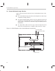
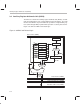
Table Of Contents
- Read This First
- Contents
- Figures
- Tables
- Examples
- Cautions
- Introduction
- Architectural Overview
- Central Processing Unit
- Memory and I/O Spaces
- Program Control
- Addressing Modes
- Assembly Language Instructions
- Instruction Set Summary
- How To Use the Instruction Descriptions
- Instruction Descriptions
- ABS
- ABS
- ADD
- ADD
- ADD
- ADD
- ADDC
- ADDC
- ADDS
- ADDS
- ADDT
- ADDT
- ADRK
- AND
- AND
- AND
- APAC
- APAC
- B
- BACC
- BANZ
- BANZ
- BCND
- BCND
- BIT
- BIT
- BITT
- BITT
- BLDD
- BLDD
- BLDD
- BLDD
- BLDD
- BLPD
- BLPD
- BLPD
- BLPD
- CALA
- CALL
- CC
- CC
- CLRC
- CLRC
- CMPL
- CMPR
- DMOV
- DMOV
- IDLE
- IN
- IN
- INTR
- LACC
- LACC
- LACC
- LACL
- LACL
- LACL
- LACT
- LACT
- LAR
- LAR
- LAR
- LDP
- LDP
- LPH
- LPH
- LST
- LST
- LST
- LST
- LT
- LT
- LTA
- LTA
- LTD
- LTD
- LTD
- LTP
- LTP
- LTS
- LTS
- MAC
- MAC
- MAC
- MAC
- MACD
- MACD
- MACD
- MACD
- MACD
- MAR
- MAR
- MPY
- MPY
- MPY
- MPYA
- MPYA
- MPYS
- MPYS
- MPYU
- MPYU
- NEG
- NEG
- NMI
- NOP
- NORM
- NORM
- NORM
- OR
- OR
- OR
- OUT
- OUT
- PAC
- POP
- POP
- POPD
- POPD
- PSHD
- PSHD
- PUSH
- RET
- RETC
- ROL
- ROR
- RPT
- RPT
- SACH
- SACH
- SACL
- SACL
- SAR
- SAR
- SBRK
- SETC
- SETC
- SFL
- SFR
- SFR
- SPAC
- SPH
- SPH
- SPL
- SPL
- SPLK
- SPLK
- SPM
- SQRA
- SQRA
- SQRS
- SQRS
- SST
- SST
- SUB
- SUB
- SUB
- SUB
- SUBB
- SUBB
- SUBC
- SUBC
- SUBS
- SUBS
- SUBT
- SUBT
- TBLR
- TBLR
- TBLR
- TBLW
- TBLW
- TBLW
- TRAP
- XOR
- XOR
- XOR
- ZALR
- ZALR
- On-Chip Peripherals
- Synchronous Serial Port
- Asynchronous Serial Port
- TMS320C209
- Register Summary
- TMS320C1x/C2x/C2xx/C5x Instruction Set Comparison
- Program Examples
- Submitting ROM Codes to TI
- Design Considerations for Using XDS510 Emulator
- E.1 Designing Your Target System’s Emulator Connector (14-Pin Header)
- E.2 Bus Protocol
- E.3 Emulator Cable Pod
- E.4 Emulator Cable Pod Signal Timing
- E.5 Emulation Timing Calculations
- E.6 Connections Between the Emulator and the Target System
- E.7 Physical Dimensions for the 14-Pin Emulator Connector
- E.8 Emulation Design Considerations
- Glossary
- Index

Central Arithmetic Logic Section
3-9
Central Processing Unit
3.3.1 Central Arithmetic Logic Unit (CALU)
The central arithmetic logic unit (CALU), implements a wide range of arithme-
tic and logic functions, most of which execute in a single clock cycle. These
functions can be grouped into four categories:
16-bit addition
16-bit subtraction
Boolean logic operations
Bit testing, shifting, and rotating.
Because the CALU can perform Boolean operations, you can perform bit ma-
nipulation. For bit shifting and rotating, the CALU uses the accumulator. The
CALU is referred to as central because there is an independent arithmetic unit,
the auxiliary register arithmetic unit (ARAU), which is described in Section 3.4.
A description of the inputs, the output, and an associated status bit of the CALU
follows.
Inputs. The CALU has two inputs (see again Figure 3–6):
One input is always provided by the 32-bit accumulator.
The other input is provided by one of the following:
The product-scaling shifter (see subsection 3.2.2)
The input data-scaling shifter (see Section 3.1)
Output. Once the CALU performs an operation, it transfers the result to the
32-bit accumulator, which is capable of performing bit shifts of its contents. The
output of the accumulator is connected to the 32-bit output data-scaling shifter.
Through the output shifter, the accumulator’s upper and lower 16-bit words
can be individually shifted and stored to data memory.
Sign-extension mode bit. For many but not all instructions, the sign-exten-
sion mode bit (SXM), bit 10 of status register ST1, determines whether the
CALU uses sign extension during its calculations. If SXM = 0, sign extension
is suppressed. If SXM = 1, sign extension is enabled.
3.3.2 Accumulator
Once the CALU performs an operation, it transfers the result to the 32-bit accu-
mulator, which can then perform single-bit shifts or rotations on its contents.
Each of the accumulator’s upper and lower 16-bit words can be passed to the
output data-scaling shifter, where it can be shifted, and then stored in data
memory. Status bits and branch instructions associated with the accumulator
are discussed directly below.