
Calculator User Manual
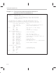
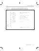
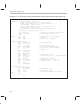
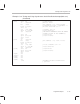
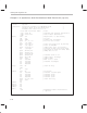
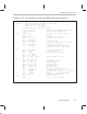
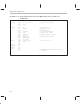
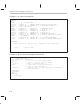
Table Of Contents
- Read This First
- Contents
- Figures
- Tables
- Examples
- Cautions
- Introduction
- Architectural Overview
- Central Processing Unit
- Memory and I/O Spaces
- Program Control
- Addressing Modes
- Assembly Language Instructions
- Instruction Set Summary
- How To Use the Instruction Descriptions
- Instruction Descriptions
- ABS
- ABS
- ADD
- ADD
- ADD
- ADD
- ADDC
- ADDC
- ADDS
- ADDS
- ADDT
- ADDT
- ADRK
- AND
- AND
- AND
- APAC
- APAC
- B
- BACC
- BANZ
- BANZ
- BCND
- BCND
- BIT
- BIT
- BITT
- BITT
- BLDD
- BLDD
- BLDD
- BLDD
- BLDD
- BLPD
- BLPD
- BLPD
- BLPD
- CALA
- CALL
- CC
- CC
- CLRC
- CLRC
- CMPL
- CMPR
- DMOV
- DMOV
- IDLE
- IN
- IN
- INTR
- LACC
- LACC
- LACC
- LACL
- LACL
- LACL
- LACT
- LACT
- LAR
- LAR
- LAR
- LDP
- LDP
- LPH
- LPH
- LST
- LST
- LST
- LST
- LT
- LT
- LTA
- LTA
- LTD
- LTD
- LTD
- LTP
- LTP
- LTS
- LTS
- MAC
- MAC
- MAC
- MAC
- MACD
- MACD
- MACD
- MACD
- MACD
- MAR
- MAR
- MPY
- MPY
- MPY
- MPYA
- MPYA
- MPYS
- MPYS
- MPYU
- MPYU
- NEG
- NEG
- NMI
- NOP
- NORM
- NORM
- NORM
- OR
- OR
- OR
- OUT
- OUT
- PAC
- POP
- POP
- POPD
- POPD
- PSHD
- PSHD
- PUSH
- RET
- RETC
- ROL
- ROR
- RPT
- RPT
- SACH
- SACH
- SACL
- SACL
- SAR
- SAR
- SBRK
- SETC
- SETC
- SFL
- SFR
- SFR
- SPAC
- SPH
- SPH
- SPL
- SPL
- SPLK
- SPLK
- SPM
- SQRA
- SQRA
- SQRS
- SQRS
- SST
- SST
- SUB
- SUB
- SUB
- SUB
- SUBB
- SUBB
- SUBC
- SUBC
- SUBS
- SUBS
- SUBT
- SUBT
- TBLR
- TBLR
- TBLR
- TBLW
- TBLW
- TBLW
- TRAP
- XOR
- XOR
- XOR
- ZALR
- ZALR
- On-Chip Peripherals
- Synchronous Serial Port
- Asynchronous Serial Port
- TMS320C209
- Register Summary
- TMS320C1x/C2x/C2xx/C5x Instruction Set Comparison
- Program Examples
- Submitting ROM Codes to TI
- Design Considerations for Using XDS510 Emulator
- E.1 Designing Your Target System’s Emulator Connector (14-Pin Header)
- E.2 Bus Protocol
- E.3 Emulator Cable Pod
- E.4 Emulator Cable Pod Signal Timing
- E.5 Emulation Timing Calculations
- E.6 Connections Between the Emulator and the Target System
- E.7 Physical Dimensions for the 14-Pin Emulator Connector
- E.8 Emulation Design Considerations
- Glossary
- Index

Task-Specific Program Code
C-21
Program Examples
Example C–14. Using Synchronous Serial Port With Codec Device (ad55.asm)
* File: ad55.asm *
* Function: Burst mode simple loop back on AD55 CODEC *
* CODEC master clock 10 MHz *
* Simple I/O at 9.6-kHz sampling *
.title ”AD55 codec simple I/O” ; Title
.copy ”init.h” ; Variable and register declaration
.copy ”vector.h” ; Vector label declaration
.text
start: clrc cnf ; Map block B0 to data memory
ldp #0h ; set DP=0
setc intm ; Disable all interrupts
splk #0000h, 60h ; Set zero wait states
out 60h,wsgr
splk #0c002h,60h ; Initialize SSP
out 60h, sspcr ; reset the serial port by writing
splk #0c032h,60h ; zeros to reset bits,
out 60h,sspcr ; enable Sync port, 1 word fifo,
; CLX/FSR as inputs. Burst mode
main: splk #08h,imr ; enable RINT interrupt
splk #0ffffh, ifr ; reset ifr flags
mar *,ar1 ; load ar1 with rx buffer
lar ar1, #rxbuf
lar ar0, #size
* 0 0 R/W’ reg_add data ; AD55 command reg. bits
*D15 14 13 12 – 8 7–0
splk #0000h, 60h ; reg0 nop
splk #0304h, 61h ; reg1 8khz sampling
splk #0200h, 62h ; default data 00
splk #0301h, 63h ; default data 01
splk #0401h, 64h ; default data 01
splk #0508h, 65h ; default data 08
splk #0001h, 66h ; secondary comm. request data
out 66h,sdtr ; request sec. comm.
out 61h,sdtr ; send reg1 data for 9.6-Khz sampling
out 60h,sdtr ; send 0x0000 after programming
clrc intm ; Enable SSP interrupts
loop: clrc xf ; clear xf flag
idle ; Wait for SSP interrupt
b loop