
Calculator User Manual
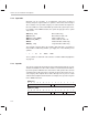
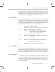
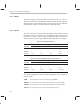
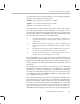
Table Of Contents
- Read This First
- Contents
- Figures
- Tables
- Examples
- Cautions
- Introduction
- Architectural Overview
- Central Processing Unit
- Memory and I/O Spaces
- Program Control
- Addressing Modes
- Assembly Language Instructions
- Instruction Set Summary
- How To Use the Instruction Descriptions
- Instruction Descriptions
- ABS
- ABS
- ADD
- ADD
- ADD
- ADD
- ADDC
- ADDC
- ADDS
- ADDS
- ADDT
- ADDT
- ADRK
- AND
- AND
- AND
- APAC
- APAC
- B
- BACC
- BANZ
- BANZ
- BCND
- BCND
- BIT
- BIT
- BITT
- BITT
- BLDD
- BLDD
- BLDD
- BLDD
- BLDD
- BLPD
- BLPD
- BLPD
- BLPD
- CALA
- CALL
- CC
- CC
- CLRC
- CLRC
- CMPL
- CMPR
- DMOV
- DMOV
- IDLE
- IN
- IN
- INTR
- LACC
- LACC
- LACC
- LACL
- LACL
- LACL
- LACT
- LACT
- LAR
- LAR
- LAR
- LDP
- LDP
- LPH
- LPH
- LST
- LST
- LST
- LST
- LT
- LT
- LTA
- LTA
- LTD
- LTD
- LTD
- LTP
- LTP
- LTS
- LTS
- MAC
- MAC
- MAC
- MAC
- MACD
- MACD
- MACD
- MACD
- MACD
- MAR
- MAR
- MPY
- MPY
- MPY
- MPYA
- MPYA
- MPYS
- MPYS
- MPYU
- MPYU
- NEG
- NEG
- NMI
- NOP
- NORM
- NORM
- NORM
- OR
- OR
- OR
- OUT
- OUT
- PAC
- POP
- POP
- POPD
- POPD
- PSHD
- PSHD
- PUSH
- RET
- RETC
- ROL
- ROR
- RPT
- RPT
- SACH
- SACH
- SACL
- SACL
- SAR
- SAR
- SBRK
- SETC
- SETC
- SFL
- SFR
- SFR
- SPAC
- SPH
- SPH
- SPL
- SPL
- SPLK
- SPLK
- SPM
- SQRA
- SQRA
- SQRS
- SQRS
- SST
- SST
- SUB
- SUB
- SUB
- SUB
- SUBB
- SUBB
- SUBC
- SUBC
- SUBS
- SUBS
- SUBT
- SUBT
- TBLR
- TBLR
- TBLR
- TBLW
- TBLW
- TBLW
- TRAP
- XOR
- XOR
- XOR
- ZALR
- ZALR
- On-Chip Peripherals
- Synchronous Serial Port
- Asynchronous Serial Port
- TMS320C209
- Register Summary
- TMS320C1x/C2x/C2xx/C5x Instruction Set Comparison
- Program Examples
- Submitting ROM Codes to TI
- Design Considerations for Using XDS510 Emulator
- E.1 Designing Your Target System’s Emulator Connector (14-Pin Header)
- E.2 Bus Protocol
- E.3 Emulator Cable Pod
- E.4 Emulator Cable Pod Signal Timing
- E.5 Emulation Timing Calculations
- E.6 Connections Between the Emulator and the Target System
- E.7 Physical Dimensions for the 14-Pin Emulator Connector
- E.8 Emulation Design Considerations
- Glossary
- Index

How To Use the Instruction Descriptions
7-14
7.2.2 Operands
Operands can be constants, or assembly-time expressions referring to
memory, I/O ports, register addresses, pointers, shift counts, and a variety of
other constants. The operands category for each instruction description de-
fines the variables used for and/or within operands in the syntax expressions.
For example, for the ADD instruction, the syntax category gives these syntax
expressions:
ADD
dma
[,
shift
] Direct addressing
ADD
dma
, 16 Direct with left shift of 16
ADD
ind
[,
shift
[, AR
n
]] Indirect addressing
ADD
ind
, 16 [, AR
n
] Indirect with left shift of 16
ADD #
k
Short immediate addressing
ADD #
lk
[,
shift
] Long immediate addressing
The operands category defines the variables
dma
,
shift
,
ind
,
n
,
k
, and
lk
. For
ind
, an indirect addressing variable, you supply one of the following seven
symbols:
* *+ *– *0+ *0– *BR0+ *BR0–
These symbols are defined in subsection 6.3.2,
Indirect Addressing Options
,
on page 6-9.
7.2.3 Opcode
The opcode category breaks down the various bit fields that make up each in-
struction word. When one of the fields contains a constant value derived direct-
ly from an operand, it will have the same name as that operand. The contents
of fields that do not directly relate to operands are given other names; the op-
code category either explains these names directly or refers you to a section
of this book that explains them in detail. For example, these opcodes are given
for the ADDC instruction:
ADDC
dma
1514131211109876543210
0
11000000 dma
ADDC
ind
[, AR
n
]
1514131211109876543210
0
11000001 ARU N NAR
Note: ARU, N, and NAR are defined in Section 6.3,
Indirect Addressing Mode
(page 6-9).