
Calculator User Manual

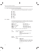
Table Of Contents
- Read This First
- Contents
- Figures
- Tables
- Examples
- Cautions
- Introduction
- Architectural Overview
- Central Processing Unit
- Memory and I/O Spaces
- Program Control
- Addressing Modes
- Assembly Language Instructions
- Instruction Set Summary
- How To Use the Instruction Descriptions
- Instruction Descriptions
- ABS
- ABS
- ADD
- ADD
- ADD
- ADD
- ADDC
- ADDC
- ADDS
- ADDS
- ADDT
- ADDT
- ADRK
- AND
- AND
- AND
- APAC
- APAC
- B
- BACC
- BANZ
- BANZ
- BCND
- BCND
- BIT
- BIT
- BITT
- BITT
- BLDD
- BLDD
- BLDD
- BLDD
- BLDD
- BLPD
- BLPD
- BLPD
- BLPD
- CALA
- CALL
- CC
- CC
- CLRC
- CLRC
- CMPL
- CMPR
- DMOV
- DMOV
- IDLE
- IN
- IN
- INTR
- LACC
- LACC
- LACC
- LACL
- LACL
- LACL
- LACT
- LACT
- LAR
- LAR
- LAR
- LDP
- LDP
- LPH
- LPH
- LST
- LST
- LST
- LST
- LT
- LT
- LTA
- LTA
- LTD
- LTD
- LTD
- LTP
- LTP
- LTS
- LTS
- MAC
- MAC
- MAC
- MAC
- MACD
- MACD
- MACD
- MACD
- MACD
- MAR
- MAR
- MPY
- MPY
- MPY
- MPYA
- MPYA
- MPYS
- MPYS
- MPYU
- MPYU
- NEG
- NEG
- NMI
- NOP
- NORM
- NORM
- NORM
- OR
- OR
- OR
- OUT
- OUT
- PAC
- POP
- POP
- POPD
- POPD
- PSHD
- PSHD
- PUSH
- RET
- RETC
- ROL
- ROR
- RPT
- RPT
- SACH
- SACH
- SACL
- SACL
- SAR
- SAR
- SBRK
- SETC
- SETC
- SFL
- SFR
- SFR
- SPAC
- SPH
- SPH
- SPL
- SPL
- SPLK
- SPLK
- SPM
- SQRA
- SQRA
- SQRS
- SQRS
- SST
- SST
- SUB
- SUB
- SUB
- SUB
- SUBB
- SUBB
- SUBC
- SUBC
- SUBS
- SUBS
- SUBT
- SUBT
- TBLR
- TBLR
- TBLR
- TBLW
- TBLW
- TBLW
- TRAP
- XOR
- XOR
- XOR
- ZALR
- ZALR
- On-Chip Peripherals
- Synchronous Serial Port
- Asynchronous Serial Port
- TMS320C209
- Register Summary
- TMS320C1x/C2x/C2xx/C5x Instruction Set Comparison
- Program Examples
- Submitting ROM Codes to TI
- Design Considerations for Using XDS510 Emulator
- E.1 Designing Your Target System’s Emulator Connector (14-Pin Header)
- E.2 Bus Protocol
- E.3 Emulator Cable Pod
- E.4 Emulator Cable Pod Signal Timing
- E.5 Emulation Timing Calculations
- E.6 Connections Between the Emulator and the Target System
- E.7 Physical Dimensions for the 14-Pin Emulator Connector
- E.8 Emulation Design Considerations
- Glossary
- Index

How To Use the Instruction Descriptions
7-13
Assembly Language Instructions
[, x] Operand x is optional.
Example:
For the syntax:
ADD
dma
, [,
shift
]
you must supply
dma
, as in the instruction:
ADD 7h
and you have the option of adding a
shift
value,
as in the instruction:
ADD 7h, 5
[, x1 [, x2]]
Operands x1 and x2 are optional, but you cannot include x2
without also including x1.
Example:
For the syntax:
ADD
ind
, [,
shift
[, AR
n
]]
you must supply
ind
, as in the instruction:
ADD *+
You have the option of including
shift
,
as in the instruction:
ADD *+, 5
If you wish to include AR
n
, you must also
include
shift
, as in:
ADD *+, 0, AR2
#
The # symbol is a prefix for constants used in immediate
addressing. For short- or long- immediate operands, it is
used in instructions where there is ambiguity with other
addressing modes.
Example:
RPT #15 uses short immediate addressing. It
causes the next instruction to be repeated 16
times. But
RPT 15 uses direct addressing.
The number of times the next instruction
repeats is determined by a value stored in
memory.
Finally, consider this code example:
MoveData BLDD DAT5, #310h ;move data at address
;referenced by DAT5 to address
;310h.
Note the optional label MoveData used as a reference in front of the instruc-
tion mnemonic. Place labels either before the instruction mnemonic on the
same line or on the preceding line in the first column. (Be sure there are no
spaces in your labels.) An optional comment field can conclude the syntax ex-
pression. At least one space is required between fields (label, mnemonic, op-
erand, and comment).