
Calculator User Manual
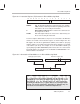
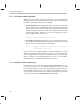
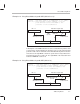
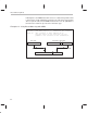
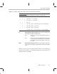
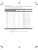
Table Of Contents
- Read This First
- Contents
- Figures
- Tables
- Examples
- Cautions
- Introduction
- Architectural Overview
- Central Processing Unit
- Memory and I/O Spaces
- Program Control
- Addressing Modes
- Assembly Language Instructions
- Instruction Set Summary
- How To Use the Instruction Descriptions
- Instruction Descriptions
- ABS
- ABS
- ADD
- ADD
- ADD
- ADD
- ADDC
- ADDC
- ADDS
- ADDS
- ADDT
- ADDT
- ADRK
- AND
- AND
- AND
- APAC
- APAC
- B
- BACC
- BANZ
- BANZ
- BCND
- BCND
- BIT
- BIT
- BITT
- BITT
- BLDD
- BLDD
- BLDD
- BLDD
- BLDD
- BLPD
- BLPD
- BLPD
- BLPD
- CALA
- CALL
- CC
- CC
- CLRC
- CLRC
- CMPL
- CMPR
- DMOV
- DMOV
- IDLE
- IN
- IN
- INTR
- LACC
- LACC
- LACC
- LACL
- LACL
- LACL
- LACT
- LACT
- LAR
- LAR
- LAR
- LDP
- LDP
- LPH
- LPH
- LST
- LST
- LST
- LST
- LT
- LT
- LTA
- LTA
- LTD
- LTD
- LTD
- LTP
- LTP
- LTS
- LTS
- MAC
- MAC
- MAC
- MAC
- MACD
- MACD
- MACD
- MACD
- MACD
- MAR
- MAR
- MPY
- MPY
- MPY
- MPYA
- MPYA
- MPYS
- MPYS
- MPYU
- MPYU
- NEG
- NEG
- NMI
- NOP
- NORM
- NORM
- NORM
- OR
- OR
- OR
- OUT
- OUT
- PAC
- POP
- POP
- POPD
- POPD
- PSHD
- PSHD
- PUSH
- RET
- RETC
- ROL
- ROR
- RPT
- RPT
- SACH
- SACH
- SACL
- SACL
- SAR
- SAR
- SBRK
- SETC
- SETC
- SFL
- SFR
- SFR
- SPAC
- SPH
- SPH
- SPL
- SPL
- SPLK
- SPLK
- SPM
- SQRA
- SQRA
- SQRS
- SQRS
- SST
- SST
- SUB
- SUB
- SUB
- SUB
- SUBB
- SUBB
- SUBC
- SUBC
- SUBS
- SUBS
- SUBT
- SUBT
- TBLR
- TBLR
- TBLR
- TBLW
- TBLW
- TBLW
- TRAP
- XOR
- XOR
- XOR
- ZALR
- ZALR
- On-Chip Peripherals
- Synchronous Serial Port
- Asynchronous Serial Port
- TMS320C209
- Register Summary
- TMS320C1x/C2x/C2xx/C5x Instruction Set Comparison
- Program Examples
- Submitting ROM Codes to TI
- Design Considerations for Using XDS510 Emulator
- E.1 Designing Your Target System’s Emulator Connector (14-Pin Header)
- E.2 Bus Protocol
- E.3 Emulator Cable Pod
- E.4 Emulator Cable Pod Signal Timing
- E.5 Emulation Timing Calculations
- E.6 Connections Between the Emulator and the Target System
- E.7 Physical Dimensions for the 14-Pin Emulator Connector
- E.8 Emulation Design Considerations
- Glossary
- Index

Indirect Addressing Mode
6-10
ister as the data memory address and then increments or decrements the
content of the current auxiliary register by the index amount.
Increment or decrement by an index amount using reverse carry. The
value in AR0 is the index amount. After the instruction uses the content of
the current auxiliary register as the data-memory address, that content is
incremented or decremented by the index amount. The addition or sub-
traction, in this case, is done with the carry propagation reversed (for
FFTs).
These four option types provide the seven indirect addressing options listed
in Table 6–1. The table also shows the instruction operand that corresponds
to each indirect addressing option and gives an example of how each option
is used.
Table 6–1. Indirect Addressing Operands
Option Operand Example
No increment or decrement * LT * loads the temporary register
(TREG) with the content of the data
memory address referenced by the
current AR.
Increment by 1 *+ LT *+ loads the temporary register
(TREG) with the content of the data
memory address referenced by the
current AR and then adds one to the
content of the current AR.
Decrement by 1 *– LT *– loads the temporary register
(TREG) with the content of the data
memory address referenced by the
current AR and then subtracts one from
the content of the current AR.
Increment by index amount *0+ LT *0+ loads the temporary register
(TREG) with the content of the data
memory address referenced by the
current AR and then adds the content
of AR0 to the content of the current AR.
Decrement by index amount
*0– LT *0– loads the temporary register
(TREG) with the content of the data
memory address referenced by the
current AR and then subtracts the con-
tent of AR0 from the content of the cur-
rent AR.