
Calculator User Manual
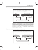
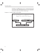
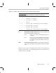
Table Of Contents
- Read This First
- Contents
- Figures
- Tables
- Examples
- Cautions
- Introduction
- Architectural Overview
- Central Processing Unit
- Memory and I/O Spaces
- Program Control
- Addressing Modes
- Assembly Language Instructions
- Instruction Set Summary
- How To Use the Instruction Descriptions
- Instruction Descriptions
- ABS
- ABS
- ADD
- ADD
- ADD
- ADD
- ADDC
- ADDC
- ADDS
- ADDS
- ADDT
- ADDT
- ADRK
- AND
- AND
- AND
- APAC
- APAC
- B
- BACC
- BANZ
- BANZ
- BCND
- BCND
- BIT
- BIT
- BITT
- BITT
- BLDD
- BLDD
- BLDD
- BLDD
- BLDD
- BLPD
- BLPD
- BLPD
- BLPD
- CALA
- CALL
- CC
- CC
- CLRC
- CLRC
- CMPL
- CMPR
- DMOV
- DMOV
- IDLE
- IN
- IN
- INTR
- LACC
- LACC
- LACC
- LACL
- LACL
- LACL
- LACT
- LACT
- LAR
- LAR
- LAR
- LDP
- LDP
- LPH
- LPH
- LST
- LST
- LST
- LST
- LT
- LT
- LTA
- LTA
- LTD
- LTD
- LTD
- LTP
- LTP
- LTS
- LTS
- MAC
- MAC
- MAC
- MAC
- MACD
- MACD
- MACD
- MACD
- MACD
- MAR
- MAR
- MPY
- MPY
- MPY
- MPYA
- MPYA
- MPYS
- MPYS
- MPYU
- MPYU
- NEG
- NEG
- NMI
- NOP
- NORM
- NORM
- NORM
- OR
- OR
- OR
- OUT
- OUT
- PAC
- POP
- POP
- POPD
- POPD
- PSHD
- PSHD
- PUSH
- RET
- RETC
- ROL
- ROR
- RPT
- RPT
- SACH
- SACH
- SACL
- SACL
- SAR
- SAR
- SBRK
- SETC
- SETC
- SFL
- SFR
- SFR
- SPAC
- SPH
- SPH
- SPL
- SPL
- SPLK
- SPLK
- SPM
- SQRA
- SQRA
- SQRS
- SQRS
- SST
- SST
- SUB
- SUB
- SUB
- SUB
- SUBB
- SUBB
- SUBC
- SUBC
- SUBS
- SUBS
- SUBT
- SUBT
- TBLR
- TBLR
- TBLR
- TBLW
- TBLW
- TBLW
- TRAP
- XOR
- XOR
- XOR
- ZALR
- ZALR
- On-Chip Peripherals
- Synchronous Serial Port
- Asynchronous Serial Port
- TMS320C209
- Register Summary
- TMS320C1x/C2x/C2xx/C5x Instruction Set Comparison
- Program Examples
- Submitting ROM Codes to TI
- Design Considerations for Using XDS510 Emulator
- E.1 Designing Your Target System’s Emulator Connector (14-Pin Header)
- E.2 Bus Protocol
- E.3 Emulator Cable Pod
- E.4 Emulator Cable Pod Signal Timing
- E.5 Emulation Timing Calculations
- E.6 Connections Between the Emulator and the Target System
- E.7 Physical Dimensions for the 14-Pin Emulator Connector
- E.8 Emulation Design Considerations
- Glossary
- Index

Indirect Addressing Mode
6-9
Addressing Modes
6.3 Indirect Addressing Mode
Eight auxiliary registers (AR0–AR7) provide flexible and powerful indirect ad-
dressing. Any location in the 64K data memory space can be accessed using
a 16-bit address contained in an auxiliary register.
6.3.1 Current Auxiliary Register
To select a specific auxiliary register, load the 3-bit auxiliary register pointer
(ARP) of status register ST0 with a value from 0 to 7. The ARP can be loaded
as a primary operation by the MAR instruction or by the LST instruction. The
ARP can be loaded as a secondary operation by any instruction that supports
indirect addressing.
The register pointed to by the ARP is referred to as the
current auxiliary register
or
current AR
. During the processing of an instruction, the content of the cur-
rent auxiliary register is used as the address at which the data-memory access
will take place. The ARAU passes this address to the data-read address bus
(DRAB) if the instruction requires a read from data memory, or it passes the
address to the data-write address bus (DWAB) if the instruction requires a
write to data memory. After the instruction uses the data value, the contents
of the current auxiliary register can be incremented or decremented by the
ARAU, which implements unsigned 16-bit arithmetic.
Normally, the ARAU performs its arithmetic operations in the decode phase of
the pipeline (when the instruction specifying the operations is being decoded).
This allows the address to be generated before the decode phase of the next
instruction. There is an exception to this rule: During processing of the NORM
instruction, the auxiliary register and/or ARP modification is done during the
execute phase of the pipeline. For information on the operation of the pipeline,
see Section 5.2 on page 5-7.
6.3.2 Indirect Addressing Options
The ’C2xx provides four types of indirect addressing options:
No increment or decrement. The instruction uses the content of the cur-
rent auxiliary register as the data memory address but neither increments
nor decrements the content of the current auxiliary register.
Increment or decrement by 1. The instruction uses the content of the
current auxiliary register as the data memory address and then incre-
ments or decrements the content of the current auxiliary register by one.
Increment or decrement by an index amount. The value in AR0 is the
index amount. The instruction uses the content of the current auxiliary reg-