
Computer Hardware Algorithm Standard User's Guide
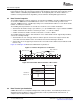
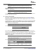
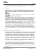
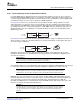
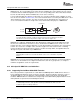
Table Of Contents
- Table of Contents
- Preface
- 1 Overview
- 2 General Programming Guidelines
- 3 Algorithm Component Model
- 3.1 Interfaces and Modules
- 3.1.1 External Identifiers
- 3.1.2 Naming Conventions
- 3.1.3 Module Initialization and Finalization
- 3.1.4 Module Instance Objects
- 3.1.5 Design-Time Object Creation
- 3.1.6 Run-Time Object Creation and Deletion
- 3.1.7 Module Configuration
- 3.1.8 Example Module
- 3.1.9 Multiple Interface Support
- 3.1.10 Interface Inheritance
- 3.1.11 Summary
- 3.2 Algorithms
- 3.3 Packaging
- 3.1 Interfaces and Modules
- 4 Algorithm Performance Characterization
- 5 DSP-Specific Guidelines
- 6 Use of the DMA Resource
- 6.1 Overview
- 6.2 Algorithm and Framework
- 6.3 Requirements for the Use of the DMA Resource
- 6.4 Logical Channel
- 6.5 Data Transfer Properties
- 6.6 Data Transfer Synchronization
- 6.7 Abstract Interface
- 6.8 Resource Characterization
- 6.9 Runtime APIs
- 6.10 Strong Ordering of DMA Transfer Requests
- 6.11 Submitting DMA Transfer Requests
- 6.12 Device Independent DMA Optimization Guideline
- 6.13 C6xxx Specific DMA Rules and Guidelines
- 6.14 C55x Specific DMA Rules and Guidelines
- 6.15 Inter-Algorithm Synchronization
- A Rules and Guidelines
- B Core Run-Time APIs
- C Bibliography
- D Glossary
www.ti.com
6.5 Data Transfer Properties
Elem0 Elem1 Elem2 Elem3
Gaps between
elements
Element index
Frame
Element size
Frame 0
Frame 1
Frame N-1
Number of
frames = N
Frame index
6.6 Data Transfer Synchronization
Data Transfer Properties
Some systems might map each logical channel to a physical channel, while in other systems, several
logical channels map to the same physical channel. This mapping is dependent on the particular system
and the number of available physical DMA channels. The important point to be made is that these
variables are transparent from the algorithm's point of view when working with logical channels.
The following definition of transfer parameters are introduced in IDMA2 to describe a DMA transfer block
as the unit of a DMA transfer. Each DMA transfer can be seen as a block made up of frames and
elements. A DMA transfer is scheduled by issuing source and destination addresses of the block and the
number of elements in each frame.
The following transfer parameters are shared across both the source and the destination:
• element size: the number of bytes per element ∈ {1, 2, 4} for IDMA2 and 1 ≤ bytes ≤ 65535 for IDMA3.
• number of elements: the number of elements per frame, 1 ≤ elements ≤ 65535
• number of frames: the number of frames in the block, 1 ≤ frames ≤ 65535
The following parameters may be shared between source and destination and if supported by hardware,
can also be set independently:
• element index: the size of the gap between elements plus the element size in bytes between two
consecutive elements within a frame. Zero indicates that element indexing is disabled.
• frame index: size of the gap in bytes between two consecutive frames within a block. Defined for 2D
transfers only.
Figure 6-1 and Figure 6-2 illustrate the DMA transfers parameters.
Figure 6-1. Transfer Properties for a 1-D Frame
Figure 6-2. Frame Index and 2-D Transfer of N-1 Frames
A DMA data transfer is accomplished independent of CPU operations. For maximum performance, the
algorithm should schedule those CPU operations that execute in parallel with the data transfers, to
complete after the data transfer completes.
64 Use of the DMA Resource SPRU352G – June 2005 – Revised February 2007
Submit Documentation Feedback