
Computer Hardware Algorithm Standard User's Guide
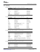
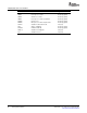
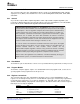
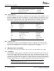
Table Of Contents
- Table of Contents
- Preface
- 1 Overview
- 2 General Programming Guidelines
- 3 Algorithm Component Model
- 3.1 Interfaces and Modules
- 3.1.1 External Identifiers
- 3.1.2 Naming Conventions
- 3.1.3 Module Initialization and Finalization
- 3.1.4 Module Instance Objects
- 3.1.5 Design-Time Object Creation
- 3.1.6 Run-Time Object Creation and Deletion
- 3.1.7 Module Configuration
- 3.1.8 Example Module
- 3.1.9 Multiple Interface Support
- 3.1.10 Interface Inheritance
- 3.1.11 Summary
- 3.2 Algorithms
- 3.3 Packaging
- 3.1 Interfaces and Modules
- 4 Algorithm Performance Characterization
- 5 DSP-Specific Guidelines
- 6 Use of the DMA Resource
- 6.1 Overview
- 6.2 Algorithm and Framework
- 6.3 Requirements for the Use of the DMA Resource
- 6.4 Logical Channel
- 6.5 Data Transfer Properties
- 6.6 Data Transfer Synchronization
- 6.7 Abstract Interface
- 6.8 Resource Characterization
- 6.9 Runtime APIs
- 6.10 Strong Ordering of DMA Transfer Requests
- 6.11 Submitting DMA Transfer Requests
- 6.12 Device Independent DMA Optimization Guideline
- 6.13 C6xxx Specific DMA Rules and Guidelines
- 6.14 C55x Specific DMA Rules and Guidelines
- 6.15 Inter-Algorithm Synchronization
- A Rules and Guidelines
- B Core Run-Time APIs
- C Bibliography
- D Glossary

www.ti.com
5.5.6 Status Bits
TMS320C55x Rules and Guidelines
The C55xx contains four status registers: ST0, ST1, ST2 and ST3.
ST0 Field Name Use Type
ACOV2 Overflow flag for AC2 Scratch (local)
ACOV3 Overflow flag for AC3 Scratch (local)
TC1, TC2 Test control flag Scratch (local)
C Carry bit Scratch (local)
ACOV0 Overflow flag for AC0 Scratch (local)
ACOV1 Overflow flag for AC1 Scratch (local)
DP bits (15 to 7) Data page pointer Scratch (local)
The following table gives the attributes for the ST1 register fields.
ST1 Field Name Use Type
BRAF Block repeat active flag Preserve (local)
CPL=1 Compiler mode bit Init (local)
XF External flag Scratch (local)
HM Host mode bit Preserve (local)
INTM Interrupt Mask Preserve (global)
M40 = 0 40/32-bit computation control for the D-unit Init (local)
SATD = 0 Saturation control for D-unit Init (local)
SXMD = 1 Sign extension mode bit for D-unit Init (local)
C16 = 0 Dual 16-bit math bit Init (local)
FRCT = 0 Fractional mode bit Init (local)
LEAD = 0 Lead bit Init (local)
T2 bits (0 to 4) Accumulator shift mode Scratch (local)
The following table describes the attributes for the ST2 register.
ST2 Field Name Use Type
ARMS=0 AR Modifier Switch Init (local)
XCNA Conditional Execute Control - Address Read-only (local)
XCND Conditional Execute Control - Data Read-only (local)
DBGM Debug enable mask bit Read-only (global)
EALLOW Emulation access enable bit Read-only (global)
RDM=0 Rounding Mode Init (local)
CDPLC Linear/Circular configuration for the CDP pointer Preserve (local)
AR7LC to AR0LC Linear/Circular configuration for the AR7 to AR0 Preserve (local)
pointer
The following table describes the attributes for the ST3 register.
ST3 Field Name Use Type
CAFRZ Cache Freeze Read-only (global)
CAEN Cache Enable Read-only (global)
CACLR Cache Clear Read-only (global)
HINT Host Interrupt Read-only (global)
SPRU352G – June 2005 – Revised February 2007 DSP-Specific Guidelines 55
Submit Documentation Feedback