
Datasheet
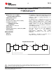
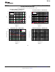


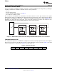
Table Of Contents
- FEATURES
- APPLICATIONS
- DESCRIPTION
- TYPICAL APPLICATION
- ABSOLUTE MAXIMUM RATINGS
- THERMAL INFORMATION
- ELECTRICAL CHARACTERISTICS
- PIN CONFIGURATION
- TYPICAL CHARACTERISTICS
- APPLICATION INFORMATION
- GENERAL DESCRIPTION
- COMMUNICATION PROTOCOL
- COMMAND REGISTER
- GLOBAL INITIALIZATION AND ADDRESS ASSIGNMENT SEQUENCE
- GLOBAL READ AND WRITE
- GLOBAL CLEAR INTERRUPT
- GLOBAL SOFTWARE RESET
- INDIVIDUAL READ AND WRITE
- TEMPERATURE REGISTER
- CONFIGURATION REGISTER
- TEMPERATURE LIMIT REGISTERS
- TIMEOUT FUNCTION
- NOISE
- SMAART WIRE INTERFACE TIMING SPECIFICATIONS
- Revision History
Host
Device
(1)
Device
(2)
Device
(N)
RX
TX
Interface Logic Interface Logic Interface Logic
RX RX RX
TX TX TX
Host
Device
(1)
Device
(2)
Device
(N)
RX
TX
Interface Logic Interface Logic Interface Logic
RX RX RX
TX TX TX
Host
Device
(1)
Device
(2)
Device
(N)
RX
TX
Interface Logic Interface Logic Interface Logic
RX RX RX
TX TX TX
TMP104
SBOS564A –NOVEMBER 2011– REVISED NOVEMBER 2011
www.ti.com
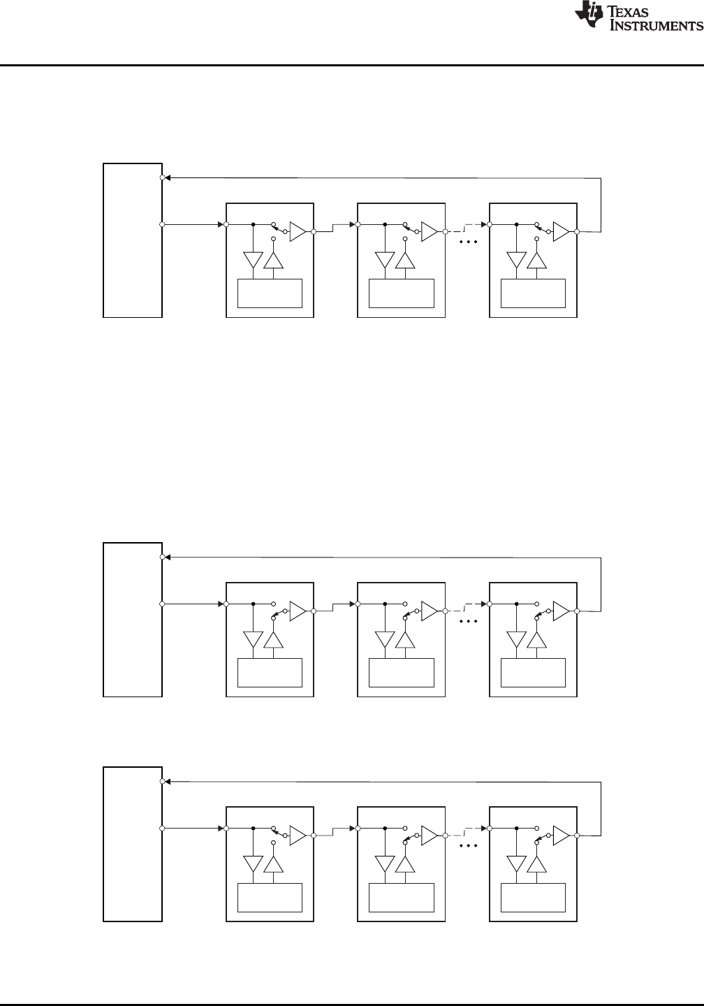
GLOBAL INITIALIZATION AND ADDRESS ASSIGNMENT SEQUENCE
At device power-up, every TMP104 in the daisy-chain is connected in transparent mode, as shown in Figure 7.
The host must send the initialization command (P7-P0 = 10001100) in order for the bus to program its internal
address depending on the number of devices on the bus.
Figure 7. TMP104 Daisy-Chain: Bus Status at Start of Global Initialization
Each TMP104 in the chain interprets the initialization command byte and disconnects the chain, as shown in
Figure 8. The host must then send the address assignment command, consisting of P7-P4 = 1001 and P3-P0 =
0000, where P3-P0 represents the address of the first device in the chain; this word is stored internally as its
device ID. The first device increments the unit in the device address and then reconnects the bus, as shown in
Figure 9. This address is then sent to the next device in the chain. Once all devices on the chain have received
the respective addresses, the host receives the last programmed address on the chain + 1. The host can use
this information to determine the total number of devices in the chain and the respective address of each device.
After the initialization sequence, every device can be addressed individually or through global commands. This
global initialization sequence is a requirement and must be performed before any other communication.
Figure 8. TMP104 Daisy-Chain: Bus Status at Start of Address Assignment
Figure 9. TMP104 Daisy-Chain: Bus Status After First Device Address Assignment
8 Submit Documentation Feedback Copyright © 2011, Texas Instruments Incorporated
Product Folder Link(s): TMP104