
Datasheet
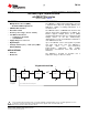
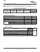

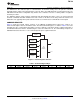

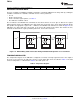
Table Of Contents
- FEATURES
- APPLICATIONS
- DESCRIPTION
- TYPICAL APPLICATION
- ABSOLUTE MAXIMUM RATINGS
- THERMAL INFORMATION
- ELECTRICAL CHARACTERISTICS
- PIN CONFIGURATION
- TYPICAL CHARACTERISTICS
- APPLICATION INFORMATION
- GENERAL DESCRIPTION
- COMMUNICATION PROTOCOL
- COMMAND REGISTER
- GLOBAL INITIALIZATION AND ADDRESS ASSIGNMENT SEQUENCE
- GLOBAL READ AND WRITE
- GLOBAL CLEAR INTERRUPT
- GLOBAL SOFTWARE RESET
- INDIVIDUAL READ AND WRITE
- TEMPERATURE REGISTER
- CONFIGURATION REGISTER
- TEMPERATURE LIMIT REGISTERS
- TIMEOUT FUNCTION
- NOISE
- SMAART WIRE INTERFACE TIMING SPECIFICATIONS
- Revision History
S S S
1 1 1 10 0 0 0
P0 D0P1 D1P2 D2P3 D3P4 D4P5 D5P6 D6P7 D7P P P
Calibration Byte (55h) Command with Address Pointer Register Data (8 LSBs)
S
P
= Start Condition of SMAART Wire Protocol
= Stop Condition of SMAART Wire Protocol
1-bit default delay
for bus direction change.
Driven by TMP104
TMP104
SBOS564A –NOVEMBER 2011– REVISED NOVEMBER 2011
www.ti.com
APPLICATION INFORMATION
GENERAL DESCRIPTION
The TMP104 is a digital output temperature sensor in a wafer chip-scale package (WCSP) that is optimal for
thermal management and thermal profiling. The TMP104 includes a SMAART wire interface that is capable of
communicating in a daisy-chain with up to 16 devices on a single bus. The interface requires two pins from the
host; the first device in the daisy-chain receives data from the host and the last device in the daisy-chain returns
data to the host. In addition, the TMP104 has the capability of executing multiple device access (MDA)
commands that allow multiple TMP104s to respond to a single global bus command. MDA commands reduce
communication time and power in a bus that contains multiple TMP104 devices. The TMP104 is specified over a
temperature range of –40ºC to +125ºC.
The TMP104 also has the capability of configuring the bus in a transparent mode, where the input from the host
is sent directly to the next device in the chain without delay. Additionally, the TMP104 can disconnect the chain
and create a serial communication controlled by each TMP104 on the bus, thereby allowing each device to have
configurable addressing and interrupt capabilities. The input pin, RX, is a high-impedance node. The output pin,
TX, has an internal push-pull output stage that can drive the host to GND or V+.
After an initialization sequence, each device on the bus is programmed with its own interface address that allows
it to respond to its own address and also respond to general commands that permit the user to read or write to all
of the devices on the bus without having to send its individual address and command to each individual device.
The temperature sensor in the TMP104 is the chip itself. Thermal paths run through the package bumps as well
as the package. The lower thermal resistance of metal causes the bumps to provide the primary thermal path. To
maintain accuracy in applications that require air or surface temperature measurement, care should be taken to
isolate the package from ambient air temperature. A thermally-conductive adhesive can help to achieve accurate
surface temperature measurement.
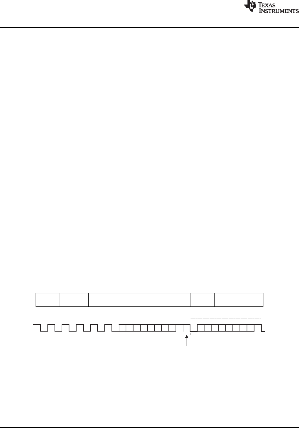
COMMUNICATION PROTOCOL
Each communication of the SMAART wire protocol consists of 8-bit words, transferred least significant bit (LSB)
first. Each 8-bit word begins with a Start bit that is logic low, and ends with a Stop bit that is logic high. By using
a Start bit and Stop bit for each 8-bit word, the TMP104 can calibrate each word and maintain synchronous
communication throughout the process. The host commences the communication by sending a Start bit followed
by the calibration byte (55h), allowing the TMP104 to sync to the baud rate of the host, followed by the Stop bit.
Then, another Start bit is sent, followed by the command register byte and a Stop bit. Finally, a third Start bit is
sent followed by the data byte, where master sends data if the instruction is a write command, or the TMP104
breaks the chain and sends data if the instruction is a read command. The process finishes with a Stop bit. The
sequence is shown in Table 1 and Figure 5.
Table 1. Communication Format
Command Data
Start bit Calibration Stop bit Start bit Stop bit Start bit Stop bit
byte byte
Figure 5. Generic Communication BitStream
6 Submit Documentation Feedback Copyright © 2011, Texas Instruments Incorporated
Product Folder Link(s): TMP104