
Datasheet
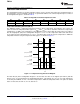

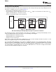

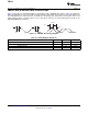


Table Of Contents
- FEATURES
- APPLICATIONS
- DESCRIPTION
- TYPICAL APPLICATION
- ABSOLUTE MAXIMUM RATINGS
- THERMAL INFORMATION
- ELECTRICAL CHARACTERISTICS
- PIN CONFIGURATION
- TYPICAL CHARACTERISTICS
- APPLICATION INFORMATION
- GENERAL DESCRIPTION
- COMMUNICATION PROTOCOL
- COMMAND REGISTER
- GLOBAL INITIALIZATION AND ADDRESS ASSIGNMENT SEQUENCE
- GLOBAL READ AND WRITE
- GLOBAL CLEAR INTERRUPT
- GLOBAL SOFTWARE RESET
- INDIVIDUAL READ AND WRITE
- TEMPERATURE REGISTER
- CONFIGURATION REGISTER
- TEMPERATURE LIMIT REGISTERS
- TIMEOUT FUNCTION
- NOISE
- SMAART WIRE INTERFACE TIMING SPECIFICATIONS
- Revision History
TX RX
GND V+
C
F
0.1 F³ m
Supply Voltage
TMP104
www.ti.com
SBOS564A –NOVEMBER 2011– REVISED NOVEMBER 2011
TEMPERATURE LIMIT REGISTERS
The T
HIGH
and T
LOW
registers are used to store the temperature limit thresholds for the TMP104 watchdog
function. At the end of each temperature measurement, the TMP104 compares the temperature results to each
of these limits. If the temperature result is greater than the T
HIGH
limit, then the FH bit in the Configuration
Register is set to '1'. If the temperature result is less than the T
LOW
limit, then the FL bit in the Configuration
Register is set to '1'; see Figure 11.
Table 8 and Table 9 describe the format for the T
HIGH
and T
LOW
registers. Power-up reset values for T
HIGH
and
T
LOW
are: T
HIGH
= +60°C and T
LOW
= –10°C. The format of the data for T
HIGH
and T
LOW
is the same as for the
Temperature Register.
Table 8. T
HIGH
Register
D7 D6 D5 D4 D3 D2 D1 D0
H7 H6 H5 H4 H3 H2 H1 H0
Table 9. T
LOW
Register
D7 D6 D5 D4 D3 D2 D1 D0
L7 L6 L5 L4 L3 L2 L1 L0
TIMEOUT FUNCTION
A timeout mechanism is implemented on the TMP104 to allow for re-synchronization of the SMAART wire
interface if synchronization between the host and the TMP104 is lost for 28 ms (typical). If the timeout period
expires between the calibration byte and the command byte, or between the command byte and any data byte,
or between any data bytes, the TMP104 resets the SMAART wire interface circuitry so that it expects the baud
rate calibration command to restart. Every time a byte is transmitted on the SMAART wire interface, this timeout
period restarts.
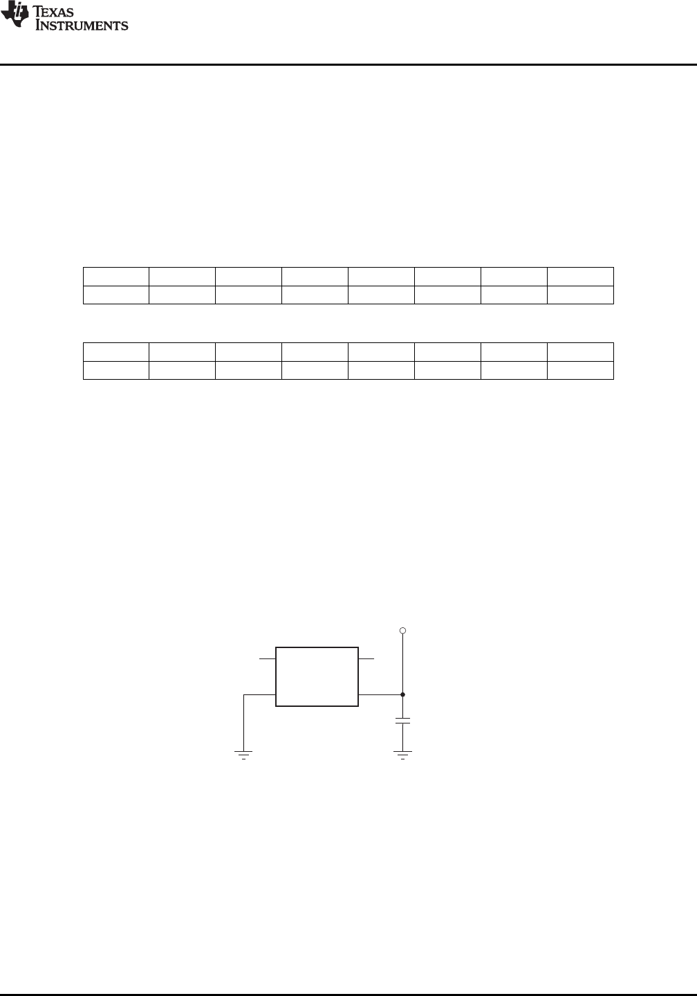
NOISE
The TMP104 is a very low-power device and generates very low noise on the supply bus. Applying a bypass
capacitor to the V+ pin of the TMP104 can further reduce any noise the TMP104 might propagate to other
components. C
F
in Figure 14 should be greater than 0.1 μF.
Figure 14. Noise Reduction
Copyright © 2011, Texas Instruments Incorporated Submit Documentation Feedback 15
Product Folder Link(s): TMP104