
Datasheet
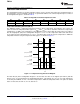


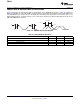


Table Of Contents
- FEATURES
- APPLICATIONS
- DESCRIPTION
- TYPICAL APPLICATION
- ABSOLUTE MAXIMUM RATINGS
- THERMAL INFORMATION
- ELECTRICAL CHARACTERISTICS
- PIN CONFIGURATION
- TYPICAL CHARACTERISTICS
- APPLICATION INFORMATION
- GENERAL DESCRIPTION
- COMMUNICATION PROTOCOL
- COMMAND REGISTER
- GLOBAL INITIALIZATION AND ADDRESS ASSIGNMENT SEQUENCE
- GLOBAL READ AND WRITE
- GLOBAL CLEAR INTERRUPT
- GLOBAL SOFTWARE RESET
- INDIVIDUAL READ AND WRITE
- TEMPERATURE REGISTER
- CONFIGURATION REGISTER
- TEMPERATURE LIMIT REGISTERS
- TIMEOUT FUNCTION
- NOISE
- SMAART WIRE INTERFACE TIMING SPECIFICATIONS
- Revision History
Measured
Temperature
T
HIGH
T
LOW
FH Bit
(Transparent Mode)
Read of Configuration Register
Time
FL Bit
(Transparent Mode)
FH Bit
(Latch Mode)
FL Bit
(Latch Mode)
TMP104
SBOS564A –NOVEMBER 2011– REVISED NOVEMBER 2011
www.ti.com
CONFIGURATION REGISTER
The Configuration Register is an 8-bit read/write register used to store bits that control the operational modes of
the temperature sensor. Read/write operations are performed LSB first. The format and power-up/reset value of
the Configuration Register is shown in Table 6.
Table 6. Configuration and Power-Up/Reset Format
D7 D6 D5 D4 D3 D2 D1 D0
INT_EN CR1 CR0 FH FL LC M1 M0
0 0 0 0 0 0 1 0
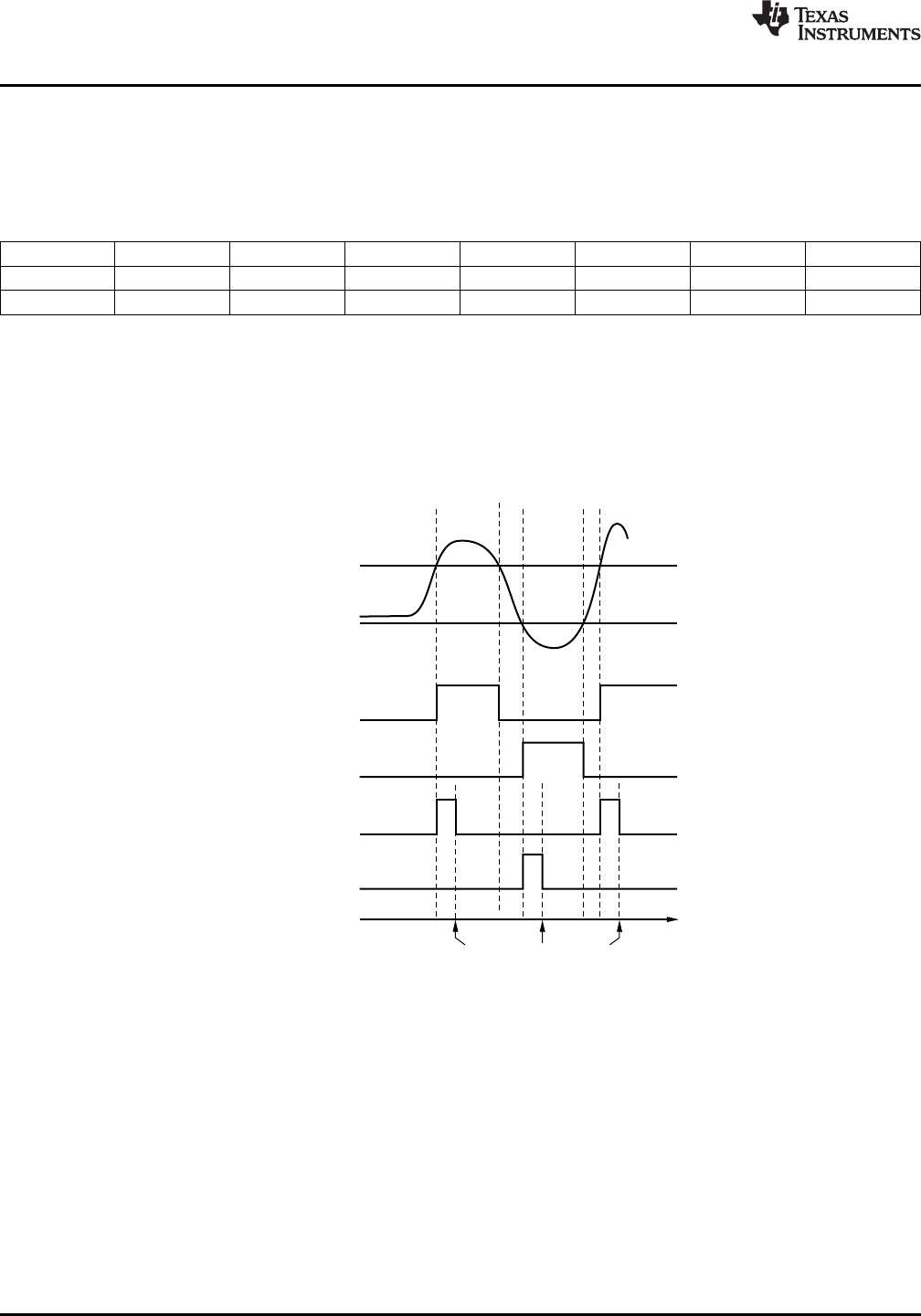
Temperature Watchdog Function (FH, FL)
The TMP104 contains a watchdog function that monitors device temperature and compares the result to the
values stored in the temperature limit registers (T
HIGH
and T
LOW
) in order to determine if the device temperature
is within these set limits. If the temperature of the TMP104 becomes greater than the value in the T
HIGH
register,
then the flag-high bit (FH) in the Configuration Register is set to '1'. If the temperature falls below value in the
T
LOW
register, then the flag-low bit (FL) is set to '1'. If both flag bits remain '0', then the temperature is within the
temperature window set by the temperature limit registers, as shown in Figure 11.
Figure 11. Temperature Flag Functional Diagram
The latch bit (LC) in the Configuration Register is used to latch the value of the flag bits (FH and FL) until the
master issues a read command to the Configuration Register. The flag bits are set to '0' if a read command is
received by the TMP104, or if LC = 0 and the temperature is within the temperature limits. The power-on default
values for these bits are FH = 0, FL = 0, and LC = 0.
12 Submit Documentation Feedback Copyright © 2011, Texas Instruments Incorporated
Product Folder Link(s): TMP104