
Datasheet


AM1808
SPRS653E –FEBRUARY 2010–REVISED MARCH 2014
www.ti.com
6.14.2.5 SATA Interface Clock Source requirements
A high-quality, low-jitter differential clock source is required for the SATA PHY. The SATA interface
requires a LVDS differential clock source to be provided at signals SATA_REFCLKP and
SATA_REFCLKN. The clock source should be placed physically as close to the processor as possible.
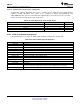
Table 6-43 shows the requirements for the clock source.
Table 6-43. SATA Input Clock Source Requirements
PARAMETER MIN TYP MAX UNIT
Clock Frequency
(1)
75 375 MHz
Jitter 50 ps pk-pk
Duty Cycle 40 60 %
Rise/Fall Time 700 ps
(1) Discrete clock frequency points are supported based on the PLL multiplier used in the SATA PHY.
6.14.3 SATA Unused Signal Configuration
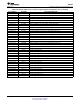
If the SATA interface is not used, the SATA signals should be configured as shown below.
Table 6-44. Unused SATA Signal Configuration
SATA Signal Name Configuration if SATA peripheral is not used
SATA_RXP No Connect
SATA_RXN No Connect
SATA_TXP No Connect
SATA_TXN No Connect
SATA_REFCLKP No Connect
SATA_REFCLKN No Connect
SATA_MPSWITCH May be used as GPIO or other peripheral function
SATA_CP_DET May be used as GPIO or other peripheral function
SATA_CP_POD May be used as GPIO or other peripheral function
SATA_LED May be used as GPIO or other peripheral function
SATA_REG No Connect
SATA_VDDR No Connect
SATA_VDD Prior to silicon revision 2.0, this supply must be connected to a static 1.2V nominal supply. For silicon
revision 2.0 and later, this supply may be left unconnected for additional power conservation.
SATA_VSS Vss
132 Peripheral Information and Electrical Specifications Copyright © 2010–2014, Texas Instruments Incorporated
Submit Documentation Feedback
Product Folder Links: AM1808