
Datasheet


AM1808
www.ti.com
SPRS653E –FEBRUARY 2010–REVISED MARCH 2014
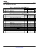
Table 6-18. Timing Requirements for EMIFA Asynchronous Memory Interface
(1)
1.2V 1.1V 1.0V
NO. UNIT
MIN MAX MIN MAX MIN MAX
READS and WRITES
E t
c(CLK)
Cycle time, EMIFA module clock 6.75 13.33 20 ns
2 t
w(EM_WAIT)
Pulse duration, EM_WAIT assertion and deassertion 2E 2E 2E ns
READS
12 t
su(EMDV-EMOEH)
Setup time, EM_D[15:0] valid before EM_OE high 3 5 7 ns
13 t
h(EMOEH-EMDIV)
Hold time, EM_D[15:0] valid after EM_OE high 0 0 0 ns
t
su (EMOEL-
Setup Time, EM_WAIT asserted before end of Strobe
14 4E+3 4E+3 4E+3 ns
EMWAIT)
Phase
WRITES
t
su (EMWEL-
Setup Time, EM_WAIT asserted before end of Strobe
28 4E+3 4E+3 4E+3 ns
EMWAIT)
Phase
(1) E = EMA_CLK period or in ns. EMA_CLK is selected either as SYSCLK3 or the PLL0 output clock divided by 4.5. As an example, when
SYSCLK3 is selected and set to 100MHz, E=10ns
Copyright © 2010–2014, Texas Instruments Incorporated Peripheral Information and Electrical Specifications 103
Submit Documentation Feedback
Product Folder Links: AM1808