
Evaluation Module User's Guide

2.2 Default Configuration and Connections
2.2.1 USB-MODEVM
2.2.2 TLV320AIC3107EVM Jumpers and Switches
www.ti.com
EVM Description and Basics
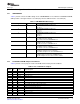
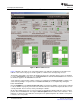
Table 1 provides a list of the SW2 settings on the USB-MODEVM. For use with the TLV320AIC3107EVM,
SW-2 positions 1 through 7 must be set to ON (LO), whereas SW-2.8 must be set to OFF (HI).
Table 1. USB-MODEVM SW2 Settings
SW-2 Switch Number Label Switch Description
1 A0 USB-MODEVM EEPROM I
2
C Address A0
ON: A0 = 0
OFF: A0 = 1
2 A1 USB-MODEVM EEPROM I
2
C Address A1
ON: A1 = 0
OFF: A1 = 1
3 A2 USB-MODEVM EEPROM I
2
C Address A2
ON: A2 = 0
OFF: A2 = 1
4 USB I
2
S™ I
2
S Bus Source Selection
ON: I
2
S Bus connects to TAS1020
OFF: I
2
S Bus connects to USB-MODEVM J14
5 USB MCK I
2
S Bus MCLK Source Selection
ON: MCLK connects to TAS1020
OFF: MCLK connects to USB-MODEVM J14
6 USB SPI SPI Bus Source Selection
ON: SPI Bus connects to TAS1020
OFF: SPI Bus connects to USB-MODEVM J15
7 USB RST RST Source Selection
ON: EVM Reset Signal comes from TAS1020
OFF: EVM Reset Signal comes from USB-MODEVM J15
8 EXT MCK External MCLK Selection
ON: MCLK Signal is provided from USB-MODEVM J10
OFF: MCLK Signal comes from either selection of SW2-5
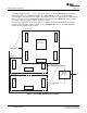
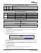
Table 2 provides a list of jumpers found on the EVM and their factory default conditions.
Table 2. List of Stand-alone Jumpers
Jumper Jumper Default
Number Type Position Jumper Description
W1 2-pin soldered AVDD_ADC power
W2 2-pin soldered DRVDD power (DRVDD1 on EVM).
W3 2-pin soldered DRVDD power (DRVDD2 on EVM).
W3 2-pin soldered AVDD_DAC power.
W5 2-pin soldered SPVDD power.
W7 2-pin soldered DVDD power.
W8 2-pin soldered IOVDD power.
W9 3-pin 2-3 Mic bias select. Connect 1-2 to use AIC3107 Mic Bias. Connect 2-3 to use EVM 3.3V Mic Bias.
W10 2-pin Open Connect EVM Onboard Mic to AIC3107 MIC3R input.
W11 2-pin Open Connect EVM Onboard Mic to AIC3107 MIC3L input.
W12 2-pin Open Enable 16-ohm load for HPL output test.
W13 2-pin Open Enable 16-ohm load for HPR output test.
W14 3-pin 1-2 IOVDD select. Connect 1-2 for IOVDD=+1.8V. Connect 2-3 for IOVDD=+3.3V.
W15 2-pin Open GPIO1 access point.
W16 2-pin Installed Software reset enable.
SLAU261 – November 2008 TLV320AIC3107EVM-K 5
Submit Documentation Feedback