
Evaluation Module User's Guide

A.3 Power Supply Connector Pin Header, J15
www.ti.com
Power Supply Connector Pin Header, J15
Note that P5 comprises the signals needed for an I
2
S serial digital audio interface; the control interface
(I
2
C and RESET) signals are routed to P4. I
2
C is actually routed to both connectors; however, the device
is connected only to P4.
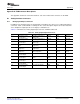
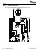
J15 provides connection to the common power bus for the TLV320AIC3107EVM. Power is supplied on the
pins listed in Table A-3 .
Table A-3. Power Supply Pinout
Signal Pin Number Signal
NC J15.1 J15.2 NC
+5VA J15.3 J15.4 NC
DGND J15.5 J15.6 AGND
DVDD (1.8V) J15.7 J15.8 NC
IOVDD (3.3V) J15.9 J15.10 NC
The TLV320AIC3107EVM-K motherboard (the USB-MODEVM Interface board) supplies power to J15 of
the TLV320AIC3107EVM. Power for the motherboard is supplied either through its USB connection or via
terminal blocks on that board.
SLAU261 – November 2008 EVM Connector Descriptions 35
Submit Documentation Feedback