
Calculator User Manual


EVMPosition2
EVMPosition1
TLV320AIC12KEVMB/14KEVMB
ControlInterface
TAS1020B
USB8051
Microcontroller
USB
I C
2
SMARTDM
AudioInterface
TLV320AIC12K/14K
Kit Operation
www.ti.com
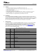
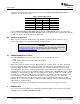
Figure 1. TLV320AIC12KEVMB-K/14KEVMB-K Block Diagram
The USB-MODEVM Interface board is intended to be used in USB mode, where control of the installed
EVM is accomplished using the onboard USB controller device. Provision is made, however, for driving all
the data buses (I
2
C, PCM/ SMARTDM™) externally. The source of these signals is controlled by SW2 on
the USB-MODEVM. Refer to Table 6 for details on the switch settings.
Additionally, SW3 on the USB-MODEVM (IOVDD SELECT) must be set up to 3.3V (SW3 position 1 on,
SW3 positions 2-8 off).
TLV320AIC12KEVMB-K and TLV320AIC14KEVMB-K User's Guide8 SLAU229B – October 2007 – Revised August 2008
Submit Documentation Feedback