
Calculator User Manual


3 Digital Interface
Digital Interface
www.ti.com
Table 1. Analog Interface Pinout (continued)
PIN NUMBER SIGNAL DESCRIPTION
J2.2 INP2 Noninverting analog input 2
J2.3 NC Not Connected
J2.4 NC Not Connected
J2.5 NC Not Connected
J2.6 NC Not Connected
J2.7 INM1 Inverting analog input 1
J2.8 INP1 Noninverting analog input 1
J2.9 AGND Analog Ground
J2.10 NC Not Connected
J2.11 AGND Analog Ground
J2.12 NC Not Connected
J2.13 AGND Analog Ground
J2.14 NC Not Connected
J2.15 NC Not Connected
J2.16 NC Not Connected
J2.17 AGND Analog Ground
J2.18 NC Not Connected
J2.19 AGND Analog Ground
J2.20 NC Not Connected
In addition to the analog headers, the analog inputs and outputs may also be accessed through alternate
connectors, either screw terminals or audio jacks. The microphone input is also tied to J8 and the headset
output tied to J11. Table 2 summarizes the screw terminals available on the
TLV320AIC12KEVMB/14KEVMB.
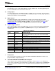
Table 2. Alternate Analog Connectors
DESIGNATOR PIN 1 PIN 2 PIN3
J6 OUTP1 OUTM1
J7 OUTP2 OUTMV OUTP3
J9 INP2 INM2
J10 INM1 INP1
The TLV320AIC12KEVMB/14KEVMB is designed to easily interface with multiple control platforms.
Samtec part numbers SSW-110-22-F-D-VS-K and TSM-110-01-T-DV-P provide a convenient 10-pin dual
row header/socket combination at J4 and J5. These headers/sockets provide access to the digital control
and serial data pins of the device. Consult Samtec at www.samtec.com or call 1-800- SAMTEC-9 for a
variety of mating connector options. Table 3 summarizes the digital interface pinout for the
TLV320AIC12KEVMB/14KEVMB.
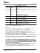
Table 3. Digital Interface Pinout
PIN NUMBER SIGNAL DESCRIPTION
J4.1 NC Not Connected
J4.2 NC Not Connected
J4.3 NC Not Connected
J4.4 DGND Digital Ground
J4.5 NC Not Connected
TLV320AIC12KEVMB-K and TLV320AIC14KEVMB-K User's Guide4 SLAU229B – October 2007 – Revised August 2008
Submit Documentation Feedback