
Calculator User Manual


6.8.5 Control Register 5 Tab
6.8.6 Control Register 6 Tab
Kit Operation
www.ti.com
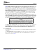
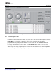
are merely for illustration; what is actually written to registers 4A and 4B are the values of P, M and N
only. The USB-MODEVM Audio Interface Configuration is set up for an MCLK=11.2896 MHz, so P, M
and N must satisfy the FS equation and the SCLK equation in Turbo Mode for that configuration. If using
the External Audio Interface Configuration, the divider values can be set to anything specified in the
TLV320AIC12K/14K datasheet.
Figure 10. Control Register 4 Tab
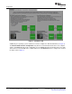
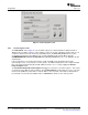
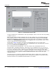
The Control Register 5 Tab (Figure 11 ) has several gain controls. The ADC PGA and DAC PGA gain
knobs range from -42dB to 20dB and each have a MUTE button. The gain knobs and the respective
MUTE buttons write to register 5A for the ADC PGA and to register 5B for the DAC PGA. Sliders are
provided for the Input Buffer Gain (0dB to 24dB) and the Digital Sidetone Gain (-21dB to -3dB w/ MUTE)
and they both share register 5C. For convenience, the corresponding register for each control is provided
to the right of the tab. An 'x' denotes the bits modified by the corresponding control.
Figure 11. Control Register 5 Tab
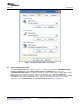
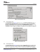
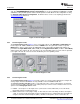
The Control Register 6 Tab (Figure 12 ) provides controls to select the analog input and to configure the
analog outputs. Note that OUTP2/P3 are only available on the TLV320AIC12/12K. The
TLV320AIC12KEVMB/14KEVMB provides a 1/8" audio jack (J8) to connect a microphone, an on-board
electret microphone (MK1) and another 1/8" audio jack (J11) to connect a stereo headset. There are four
options for the Analog Input Select control:
a. INP/M1 - selects input 1 as the input source (connected to screw terminal J10). To use this mode,
jumper W11 must be installed on pins 2-3.
b. MICIN self-biased to 1.35V (single-ended) - In this mode, the device internally self-biases the input to
1.35V. To use this mode, jumper W11 must be installed on pins 2-3. Jumper W12 must be installed if
using the on-board electret microphone (MK1), otherwise a microphone can be connected to J8.
18 TLV320AIC12KEVMB-K and TLV320AIC14KEVMB-K User's Guide SLAU229B – October 2007 – Revised August 2008
Submit Documentation Feedback