
Calculator User Manual


6.8.2 Control Register 2 Tab
Kit Operation
www.ti.com
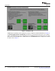
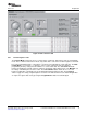
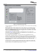
Figure 7. Control Register 1 Tab
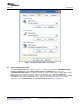
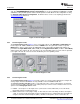
The Turbo Mode control (Figure 8 ) sets the SCLK frequency to 16 × FS × (number of devices) × mode or
MCLK ÷ P, where number of devices is the number of codecs in cascade (default=1) and the mode is 1 for
continuous data transfer mode and 2 for programming mode. The Host Port Control can be used to
assign different functions to the SDA pin or to set SCL and SDA for I2C or S2C. When using the
USB-MODEVM Audio Interface Configuration the Host Port Control must be set to SDA/SCL are I2C
interface pins.
If the host interface is not needed, the two pins of SCL and SDA can be programmed to become
general-purpose I/Os. If selected to be used as I/O pins, the SDA and SCL pins become output and input
pins respectively, determined by D1 and D0. SDA can then be set to 1 or 0 by toggling the General
Purpose Output control.
The Decimation/Interpolation filter bypass button bypasses the filters selected in register 1. This can be
useful when using a DSP to apply such filters. The I
2
C Base Address control allows the user to select the
first three bits (MSB first) of the device's 7-bit I
2
C address. The last 4 bits of the address will depend on
the automatic cascade detection (ACD) feature of SMARTDM™, which sets the device position.
16 TLV320AIC12KEVMB-K and TLV320AIC14KEVMB-K User's Guide SLAU229B – October 2007 – Revised August 2008
Submit Documentation Feedback