
Calculator User Manual


6.3 USB-MODEVM Interface Board
6.4 Program Description
Kit Operation
www.ti.com
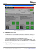
Figure 2. Default Software Screen
The simple diagram shown in Figure 1 shows only the basic features of the USB-MODEVM Interface
board. The board is built around a TAS1020B streaming audio USB controller with an 8051-based core.
The board features two positions for modular EVMs, or one double-wide serial modular EVM may be
installed.
Since the TLV320AIC12KEVMB/14KEVMB is a double-wide modular EVM, it is installed with connections
to both EVM positions, which connects the TLV320AIC12K/14K digital control interface to the I
2
C port
realized using the TAS1020B, as well as the TAS1020B digital audio interface.
In the factory configuration, the board is ready to use with the TLV320AIC12KEVMB/14KEVMB. To view
all the functions and configuration options available on the USB-MODEVM board, see the USB-MODEVM
Interface Board schematic in Appendix B .
After the TLV320AIC12KEVMBK/14KEVMB-K software installation (described in Section 6.2 ) is complete,
evaluation and development with the TLV320AIC12K/14K can begin.
TLV320AIC12KEVMB-K and TLV320AIC14KEVMB-K User's Guide10 SLAU229B – October 2007 – Revised August 2008
Submit Documentation Feedback