
Datasheet


THS6226
SBOS499C –JANUARY 2011–REVISED APRIL 2011
www.ti.com
QUIESCENT CURRENT
The quiescent current of the THS6226 is dissipated in two main modules of the THS6226: the class AB and the
charge pump. B4 and B5 select the mode of operation, class AB operating with or without the charge pump
enabled, powering down the entire port, or operating in a line termination mode. Table 4 lists the details on each
bit functionality and the approximate quiescent current.
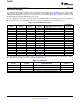
The class AB quiescent current is set by bits B6 to B9, using B4 and B5 for the power-down function, and B2 and
B3 for channel select. The approximate quiescent current for the amplifier core is shown in Table 3.
Table 3. Class AB Quiescent Current
APPROXIMATE
B6 (D3) B7 (D2) B8 (D1) B9 (D0) QUIESCENT CURRENT SETTING I
Q
(mA/Port)
0 0 0 0 ADSL2+ mode 7.6
0 0 0 1 8.7
0 0 1 0 Profile 8b mode 9.8
0 0 1 1 10.9
0 1 0 0 Profile 17a mode 12
0 1 0 1 13
0 1 1 0 14
0 1 1 1 15
1 0 0 0 16
1 0 0 1 17
1 0 1 0 Profile 30a mode 18
1 0 1 1 19
1 1 0 0 20
1 1 0 1 21
1 1 1 0 22
1 1 1 1 23
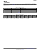
The various power modes are shown in Table 4. For all modes, when B6 through B9 are not defined, set B9 =
B8 = B7 = B6 = 0 to achieve the lowest power dissipation possible.
Table 4. Power Modes
APPROXIMATE I
Q
B4 (PD1) B5 (PD0) POWER-DOWN MODE (mA/Port)
0 0 Power-down (B9, B8, B7, B6 = 0) 0.85
0 1 Line termination mode (B9, B8, B7, B6 = 0) 4.4
1 0 Class AB driver I
Q
set by B6 to B9, class H disabled —
1 1 Class AB driver I
Q
set by B6 to B9, class H enabled —
12 Submit Documentation Feedback Copyright © 2011, Texas Instruments Incorporated
Product Folder Link(s): THS6226