
Datasheet


DATA
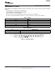
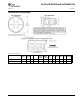
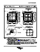
B0 B1 B2 B3 B4 B5 B6 B7 B8 B9 B10 B11
Start
Bit
Start
Bit
ChAB
Select
ChCD
Select
PD1
PD0 D3 D2 D1 D0 Parity Stop
Bit
MSB LSB
THS6226
www.ti.com
SBOS499C –JANUARY 2011–REVISED APRIL 2011
PROGRAMMING THE THS6226
Programming of the THS6226 is realized through a serial interface (pins 4 and 5) and proceeds in the following
sequence.
Two start bits are required B0 = 0 followed by B1 = 1.
B2 through B9 are used to program the THS6226.
Refer to Table 1 for the bit descriptions.
B10 (refer to Table 2) is the parity bit that controls if the word is or is not loaded.
B11 is the stop bit and should be set to B11 = 1. Figure 21 shows the sequence to be adopted.
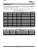
Table 1. SDATA
PARAMETER DESCRIPTION
B0, B1 Start bit
B2, B3 Channel select
B4, B5 Power-down features
B6-B9 Quiescent current setting
B10 Parity bit
B11 Stop bit
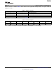
Table 2. Parity Bit
B10 ODD PARITY BIT
0 If odd, number of high bits in B2 to B9
1 If even, number of high bits in B2 to B9
Figure 21. DATA Description
Copyright © 2011, Texas Instruments Incorporated Submit Documentation Feedback 11
Product Folder Link(s): THS6226