
Datasheet


SLOS345C − JANUARY 2001 − REVISED OCTOBER 2002
5
POST OFFICE BOX 655303 • DALLAS, TEXAS 75265
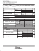
electrical characteristics over recommended operating free-air temperature range, T
A
= 25°C,
V
CC+
= 12 V, V
CC−
= GND, R
FEEDBACK
= 750 Ω, R
L
= 25 Ω (unless otherwise noted) (continued)
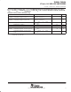
shutdown characteristics (THS6093 only)
PARAMETER TEST CONDITIONS MIN TYP MAX UNIT
V
IL(SHDN)
Shutdown pin voltage for power up
V
CC
= 12 V, GND = 6 V
(GND Pin as Reference)
0.8 V
V
IH(SHDN)
Shutdown pin voltage for power down
V
CC
= 12 V, GND = 6 V
(GND Pin as Reference)
2 V
I
CC(SHDN)
Total quiescent current when in shutdown state
V
SHDN
= 8 V, V
GND
= 6 V,
V
CC
= 12 V
0.3 0.7 mA
t
DIS
Disable time (see Note 3) V
CC
= 12 V 0.2 µs
t
EN
Enable time (see Note 3) V
CC
= 12 V 0.5 µs
I
IL(SHDN)
Shutdown pin input bias current for power up
V
SHDN
= 6 V, V
GND
= 6 V,
V
CC
= 12 V
40 100 µA
I
IH(SHDN)
Shutdown pin input bias current for power
down
V
SHDN
= 9.3 V, V
GND
= 6 V,
V
CC
= 12 V
50 100 µA
NOTE 3: Disable/enable time is defined as the time from when the shutdown signal is applied to the SHDN pin to when the supply current has
reached half of its final value.