
Datasheet


SLOS345C − JANUARY 2001 − REVISED OCTOBER 2002
2
POST OFFICE BOX 655303 • DALLAS, TEXAS 75265
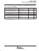
AVAILABLE OPTIONS
PACKAGED DEVICE
T
A
SOIC-8
†
(D)
SOIC-8
†
PowerPAD
(DDA)
SOIC-14
†
(D)
TSSOP-14
†
PowerPAD
(PWP)
EVALUATION
MODULES
0°C to 70°C THS6092CD THS6092CDDA THS6093CD THS6093CPWP
THS6092EVM
THS6093EVM
−40°C to 85°C THS6092ID THS6092IDDA THS6093ID THS6093IPWP —
†
All packages are available taped and reeled. Add an R-suffix to the device type (i.e., THS6092IDR).
absolute maximum ratings over operating free-air temperature (unless otherwise noted)
†
Supply voltage, V
CC+
to V
CC−
14.7 V. . . . . . . . . . . . . . . . . . . . . . . . . . . . . . . . . . . . . . . . . . . . . . . . . . . . . . . . . . . . .
Input voltage ± V
CC
. . . . . . . . . . . . . . . . . . . . . . . . . . . . . . . . . . . . . . . . . . . . . . . . . . . . . . . . . . . . . . . . . . . . . . . . . . . .
Output current (see Note 1) 350 mA. . . . . . . . . . . . . . . . . . . . . . . . . . . . . . . . . . . . . . . . . . . . . . . . . . . . . . . . . . . . . .
Differential input voltage ± 3 V. . . . . . . . . . . . . . . . . . . . . . . . . . . . . . . . . . . . . . . . . . . . . . . . . . . . . . . . . . . . . . . . . . .
Maximum junction temperature 150°C. . . . . . . . . . . . . . . . . . . . . . . . . . . . . . . . . . . . . . . . . . . . . . . . . . . . . . . . . . . .
Total power dissipation at (or below) 25°C free-air temperature See Dissipation Ratings Table. . . . . . . . . . .
Operating free-air temperature, T
A
: Commercial 0°C to 70°C. . . . . . . . . . . . . . . . . . . . . . . . . . . . . . . . . . . . . . . .
Industrial −40°C to 85°C. . . . . . . . . . . . . . . . . . . . . . . . . . . . . . . . . . . . . . . .
Storage temperature, T
stg
: Commercial −65°C to 125°C. . . . . . . . . . . . . . . . . . . . . . . . . . . . . . . . . . . . . . . . . . . .
Industrial −65°C to 125°C. . . . . . . . . . . . . . . . . . . . . . . . . . . . . . . . . . . . . . . . . . . . . .
Lead temperature 1,6 mm (1/16 inch) from case for 10 seconds 300°C. . . . . . . . . . . . . . . . . . . . . . . . . . . . . . .
†
Stresses beyond those listed under “absolute maximum ratings” may cause permanent damage to the device. These are stress ratings only, and
functional operation of the device at these or any other conditions beyond those indicated under “recommended operating conditions” is not
implied. Exposure to absolute-maximum-rated conditions for extended periods may affect device reliability.
NOTE 1: The THS6092 and THS6093 may incorporate a PowerPAD on the underside of the chip. This acts as a heatsink and must be
connected to a thermally dissipating plane for proper power dissipation. Failure to do so may result in exceeding the maximum junction
temperature which could permanently damage the device. See TI Technical Brief SLMA002 for more information about utilizing the
PowerPAD
thermally enhanced package.
DISSIPATION RATING TABLE
PACKAGE
θ
JA
θ
JC
T
A
= 25°C
§
POWER RATING
T
A
= 70°C
§
POWER RATING
T
A
= 85°C
§
POWER RATING
D-8 95°C/W
‡
38.3°C/W
‡
1.1 W 0.63 W 0.47 W
DDA 45.8°C/W 9.2°C/W 2.3 W 1.31 W 0.98 W
D-14 66.6°C/W
‡
26.9°C/W
‡
1.6 W 0.90 W 0.68 W
PWP 37.5°C/W 1.4°C/W 2.8 W 1.60 W 1.20 W
‡
This data was taken using the JEDEC proposed high-K test PCB. For the JEDEC low-K test PCB, the Θ
JA
is168°C/W for the D−8 package and
122.3°C/W for the D−14 package.
§
Power rating is determined with a junction temperature of 130°C. This is the point where distortion starts to substantially increase. Thermal
management of the final PCB should strive to keep the junction temperature at or below 125°C for best performance.
recommended operating conditions
MIN NOM MAX UNIT
Supply voltage, V
CC+
to V
CC−
Dual supply ±2.5 ±7
V
Supply voltage, V
CC+
to V
CC−
Single supply +5 +14
V
Operating free-air temperature, T
A
C-suffix 0 70
°C
Operating free-air temperature, T
A
I-suffix −40 85
°C