THS3001 High Speed Current Feedback Operational Amplifier Evaluation Module User’s Guide March 1999 Mixed-Signal Products SLOU021A
IMPORTANT NOTICE Texas Instruments and its subsidiaries (TI) reserve the right to make changes to their products or to discontinue any product or service without notice, and advise customers to obtain the latest version of relevant information to verify, before placing orders, that information being relied on is current and complete.
Preface Related Documentation From Texas Instruments J THS3001 HIGH-SPEED CURRENT-FEEDBACK OPERATIONAL AMPLIFIER (literature number SLOS217) This is the data sheet for the THS3001 operational amplifier integrated circuit that is used in the THS3001 evaluation module. FCC Warning This equipment is intended for use in a laboratory test environment only.
iv
Running Title—Attribute Reference Contents 1 General Information . . . . . . . . . . . . . . . . . . . . . . . . . . . . . . . . . . . . . . . . . . . . . . . . . . . . . . . . . . . . . 1.1 Features . . . . . . . . . . . . . . . . . . . . . . . . . . . . . . . . . . . . . . . . . . . . . . . . . . . . . . . . . . . . . . . . . . 1.2 Description . . . . . . . . . . . . . . . . . . . . . . . . . . . . . . . . . . . . . . . . . . . . . . . . . . . . . . . . . . . . . . . . 1.3 THS3001 EVM Specifications . .
vi
Chapter 1 General Information This chapter details the Texas Instruments (TI) THS3001 high-speed operational amplifier evaluation module (EVM), SLOP130. It includes a list of EVM features, a brief description of the module illustrated with a pictorial and a schematic diagram, EVM specifications, details on connecting and using the EVM, and a discussion on high-speed amplifier design considerations. Topic Page 1.1 Features . . . . . . . . . . . . . . . . . . . . . . . . . . . . . . . . . . . . . . . .
Features 1.1 Features THS3001 operational amplifier EVM features include: J J J J J J J High Bandwidth — 340 MHz, – 3 dB at ± 15 VCC & Gain = 2 ± 5-V to ± 15-V Operation Inverting and Noninverting Single-Ended Inputs Module Gain Set to + 2 (Noninverting) and –1 (Inverting) — Adjustable Through Component Change. Nominal 50-Ω Impedance Inputs and Outputs Standard SMA Miniature RF Connectors Good Example of High-Speed Amplifier Design and Layout 1.
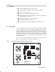
Description Figure 1–2. THS3001 Rev. A Evaluation Module J1 –VCC J2 +VCC C1 C2 GND –IN GND INVERTING TEXAS INSTRUMENTS J4 C3 R4 +IN R1 R3 U1 R5 C4 GND J3 OUT NONINVERTING GND Rev. A + + R2 SLOP130 Rev A THS3001 EVM Board The THS3001 EVM is equipped with both noninverting and inverting inputs. The noninverting input is set for a gain of 2 and the inverting input is set for a gain of 1.
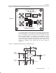
Description Figure 1–4. THS3001 Rev. A EVM Schematic VCC J1 –VCC GND VCC 1 C2 6.8 µF –VCC + 2 3 VCC J2 –IN Inverting Rev. A R2 1 kΩ R4 1 kΩ R1 49.9 Ω 2 7 – U1 THS3001 J3 +IN Noninverting C3 0.1 µF 3 R3 49.9 Ω + 4 6 R5 49.9 Ω J4 Out C4 0.1 µF C1 6.8 µF + –VCC Even though the THS3001 is a current-feedback amplifier, the gain of the EVM can easily be changed to support a particular application by simply changing the ratio of resistors R1, R4, and R5 (R1, R2, and R4 for Rev.
THS3001 EVM Specifications Note: External factors can significantly affect the overall gain of the EVM. For example, connecting test equipment with 50-Ω input impedance to the EVM output will divide the output signal level by a factor of 2 (assuming the output isolation resistor on the EVM board remains 50 Ω). Similar effects can occur at the input, depending upon how the input signal sources are configured. The gain equations given above assume no signal loss in either the input or the output.
Using The THS3001 EVM 1.4 Using The THS3001 EVM The THS3001 EVM operates from power-supply voltages ranging from ± 5 V to ± 15 V. As shipped, the inverting input gain of the module is set to 1, the noninverting input gain is set to 2, and signal inputs on the module are terminated for 50-Ω nominal impedance cables. An oscilloscope is typically used to view and analyze the EVM output signal. 1.4.
THS3001 EVM Performance 1.5 THS3001 EVM Performance Figure 1–5 shows the typical frequency response of the THS3001 EVM using the noninverting input (G = 2). Typical values show a – 3-dB bandwidth of 340 MHz with a ± 15-V power supply and 260 MHz with a ± 5-V power supply. They also show a – 0.1-dB frequency response of 17 MHz with a ± 15-V power supply and 20 MHz with a ± 5-V power supply. Figure 1–5.
General High-Speed Amplifier Design Considerations 1.6 General High-Speed Amplifier Design Considerations The THS3001 EVM layout has been designed and optimized for use with high-speed signals and can be used as an example when designing THS3001 applications. Careful attention has been given to component selection, grounding, power supply bypassing, and signal path layout.
Chapter 2 Reference This chapter includes a parts list and PCB layout illustrations for the THS3001 EVM and the THS3001 Rev. A EVM. Topic Page 2.1 THS3001 High-Speed Operational Amplifier EVM Parts List . . . . . . . 2–2 2.2 THS3001 EVM Board Layouts . . . . . . . . . . . . . . . . . . . . . . . . . . . . . . . . . . 2–2 2.3 THS3001 Rev. A High-Speed Operational Amplifier EVM Parts List 2–4 2.4 THS3001 Rev. A EVM Board Layouts . . . . . . . . . . . . . . . . . . . . . . . . . . .
THS3001 High-Speed Current-Feedback Video Operational Amplifier EVM Parts List 2.1 THS3001 High-Speed Current-Feedback Video Operational Amplifier EVM Parts List Table 2–1. THS3001 EVM Parts List Reference Description C1, C3 Capacitor, 6.8 µF, 35 V, SM C2, C4 Capacitor, 0.1 µF, ceramic, 10%, SM J1, J2, J3 Connector, SMA 50-Ω vertical PC mount, throughhole R2, R3, R4 Resistor, 49.
THS3001 EVM Board Layouts Figure 2–2. THS3001 EVM PC Board Layout – Component Side Figure 2–3.
THS3001 Rev. A High-Speed Operational Amplifier EVM Parts List 2.3 THS3001 Rev. A High-Speed Operational Amplifier EVM Parts List Table 2–2. THS3001 Rev. A EVM Parts List Reference Description Manufacturer/Digi-Key Part Number Size C1, C2 Capacitor, 6.8 µF, 35 V, SM C3, C4 Capacitor, 0.1 µF, ceramic, 10%, SM J1 Terminal Block Digi-Key ED1515–ND J2, J3, J4 Connector, SMA 50-Ω vertical PC mount, through-hole Amphenol ARF1205–ND R1, R3, R5 Resistor, 49.9 Ω, 1%, 1/8 W, SM 1206 Digi-Key P49.
THS3001 Rev. A EVM Board Layouts Figure 2–5. THS3001 Rev. A EVM PC Board Layout – Component Side Rev. A Figure 2–6. THS3001 Rev. A EVM PC Board Layout – Back Side Rev.
2-6 Reference