
Incor User's Guide Digital Amplifier TAS5518


List of Figures
1-1 Integrated PurePath Digital™ Amplifier System ......................................................................... 8
1-2 Physical Structure for TAS5518-5152K8EVM (Rough Outline) ....................................................... 9
2-1 Recommended Power-Up Sequence .................................................................................... 12
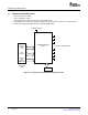
2-2 J901 and J900 Pin Numbers ............................................................................................. 12
2-3 J902 Pin Numbers ......................................................................................................... 13
2-4 J101–J107 Pin Numbers .................................................................................................. 14
2-5 J700 Pin Numbers ......................................................................................................... 15
List of Tables
1 Related Documentation From TI ........................................................................................... 6
2-1 Recommended Supply Voltages ......................................................................................... 12
2-2 J901 Pin Description ....................................................................................................... 12
2-3 J900 Pin Description ....................................................................................................... 13
2-4 J902 Pin Description ....................................................................................................... 13
2-5 J101–J107 Pin Description ................................................................................................ 14
2-6 J700 Pin Description ....................................................................................................... 15
2-7 J40 Pin Description ........................................................................................................ 15
2-8 J60 Pin Description ........................................................................................................ 16
3-1 TAS5152 Warning/Error Signal Decoding .............................................................................. 18
4 List of Figures SLEU074 – June 2006
Submit Documentation Feedback