
Digital Audio PWM Processor & Digital Amplifier User's Guide

www.ti.com
1
2
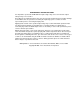
(PCBconnectortopview)
2.4 Headphone Connector (J700)
1
4
2 3
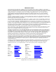
2.5 Control Interface (J40)
Headphone Connector (J700)
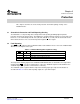
Figure 2-4. J101 . . . J107 Pin Numbers
Table 2-5. J101 . . . J107 Pin Description
PIN NO. NET-NAME AT SCHEMATICS DESCRIPTION
1 OUT-1 Speaker negative output
2 OUT-2 Speaker positive output
Figure 2-5. J700 Pin Numbers
Table 2-6. J700 Pin Description
PIN NO. NET-NAME AT SCHEMATICS DESCRIPTION
1 OUT-R Right headphone output
2 GND Ground
3 — For future use
4 OUT-L Left headphone output
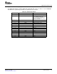
This interface connects the TAS5508-5142K7EVM board to a TI input-USB board.
Table 2-7. J40 Pin Description
PIN NO. NET-NAME AT SCHEMATICS DESCRIPTION
1 GND Ground
2 RESERVED —
3 GND Ground
4 RESET System reset (bidirectional). Activate
MUTE before RESET for quiet reset.
5 BKND-ERR Backend error (or soft reset) provides
reduced click and pop reset, without
resetting I
2
C volume register settings.
6 MUTE Ramp volume from any setting to
noiseless soft mute. Mute can also be
activated by I
2
C.
7 PDN Power down. TAS5508B will go to
power-down state when activated.
8 RESERVED —
9 RESERVED —
10 SDA I
2
C data clock
SLEU071 – June 2006 System Interfaces 11
Submit Documentation Feedback