TAS5508-5142K7EVM User’s Guide Evaluation Module for the TAS5508B Digital Audio PWM Processor and TAS5142 Digital Amplifier Power Output Stage User's Guide June 2006 SLEU071
SLEU071 – June 2006 Submit Documentation Feedback
Contents 1 2 Overview TAS5508-5142K7EVM Features.................................................................................. 6 1.2 PCB Key Map ....................................................................................................... 7 2.2 2.3 2.4 2.5 2.6 ................................................................................................................ 15 Short-Circuit Protection and Fault-Reporting Circuitry .......................................................
List of Figures 1-1 1-2 2-1 2-2 2-3 2-4 2-5 Integrated PurePath Digital™ Amplifier System ......................................................................... 6 Physical Structure for TAS5508-5142K7EVM (Rough Outline) ....................................................... 7 Recommended Power-Up Sequence ..................................................................................... 9 J901 and J900 Pin Numbers ......................................................................................
Chapter 1 SLEU071 – June 2006 Overview The TAS5508-5142K7EVM PurePath Digital™ customer evaluation amplifier module demonstrates two audio integrated circuits, TAS5508B and TAS5142, from Texas Instruments (TI). The TAS5508BPAG is a high-performance 32-bit (24-bit input) multichannel PurePath Digital pulse width modulator (PWM) based on Equibit™ technology, with a fully symmetrical AD modulation scheme. It accepts an input sample rate from 32 kHz to 192 kHz.
www.ti.com TAS5508-5142K7EVM Features 1.
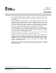
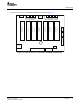
www.ti.com PCB Key Map 1.2 PCB Key Map Physical structure for the TAS5508-5142K7EVM is illustrated in Figure 1-2. J105 PSU INTERFACE (J900) J104 J103 J101 PSU INTERFACE (J901) Gate Drive Regulator 5V Regulator CHANNEL 1 CHANNEL 2 OUTPUT STAGE CHANNEL 4 OUTPUT STAGE SPEAKER OUTPUTS CHANNEL 5 OUTPUT STAGE CHANNEL 6 OUTPUT STAGE CHANNEL 7 OUTPUT STAGE SPEAKER OUTPUTS J102 OUTPUT STAGE J106 CHANNEL 3 J107 OUTPUT STAGE PSU CONTROL (J902) TAS5508B HEADPHONE OUTPUT (J700) 3.
www.ti.
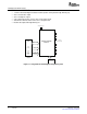
Chapter 2 SLEU071 – June 2006 System Interfaces This chapter describes the TAS5508-5142K7EVM board in regards to power supplies and system interfaces. 2.1 Power Supply (PSU) Interface (J901 and J900) The TAS5508-5142K7EVM module must be powered from external power supplies. High-end audio performance requires a stabilized power supply with low ripple voltage and low output impedance. Note: The length of power-supply cable must be minimized.
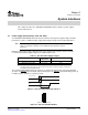
www.ti.com PSU Control Interface (J902) Table 2-2. J901 Pin Description PIN NO. NET-NAME AT SCHEMATICS DESCRIPTION 1 PVDD 2 SYSTEM Output-stage power supply 3 GND Ground 4 GND Ground System power supply Table 2-3. J900 Pin Description 2.2 PIN NO.
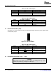
www.ti.com Headphone Connector (J700) 2 1 (PCB connector top view) Figure 2-4. J101 . . . J107 Pin Numbers Table 2-5. J101 . . . J107 Pin Description 2.4 PIN NO. NET-NAME AT SCHEMATICS 1 OUT-1 DESCRIPTION Speaker negative output 2 OUT-2 Speaker positive output Headphone Connector (J700) 1 2 3 4 Figure 2-5. J700 Pin Numbers Table 2-6. J700 Pin Description 2.5 PIN NO.
www.ti.com Control Interface (J40) Table 2-7. J40 Pin Description (continued) 12 PIN NO. NET-NAME AT SCHEMATICS 11 GND Ground 12 SCL I2C bit clock 13 RESERVED — 14 RESERVED — 15 RESERVED — 16 RESERVED — 17 GND 18 RESERVED — 19 RESERVED — 20 SD Shutdown error reporting for all channels. Activated if TAS5142 has high current or high temperature. See Chapter 3, Protection. 21 SD Shutdown reporting. Activated if one or more TAS5142 has high current or high temperature.
www.ti.com Digital Audio Interface (J60) 2.6 Digital Audio Interface (J60) The digital audio interface contains digital audio signal data (I2S), clocks, etc. Please see the TAS5508B Data Manual for signal timing and details not explained in this document. Table 2-8. J60 Pin Description PIN NO. NET-NAME AT SCHEMATICS 1 GND DESCRIPTION Ground 2 MCLK Master clock input. Low jitter system clock for PWM generation and reclocking.
www.ti.
Chapter 3 SLEU071 – June 2006 Protection This chapter describes the short-circuit protection and fault-reporting circuitry of the TAS5142 device. 3.1 Short-Circuit Protection and Fault-Reporting Circuitry The TAS5142 is a self-protecting device that provides fault reporting (including high-temperature protection and short-circuit protection). The TAS5142 is configured in back-end auto-recovery mode and, therefore, resets automatically after all errors (M1, M2, and M3 are set low).
www.ti.
Chapter 4 SLEU071 – June 2006 Related Documentation From Texas Instruments The following is a list of documents that have detailed descriptions of the integrated circuits used in the design of the TAS5508-5142K7EVM. This information can be obtained at the URL http://www.ti.com.
EVALUATION BOARD/KIT IMPORTANT NOTICE Texas Instruments (TI) provides the enclosed product(s) under the following conditions: This evaluation board/kit is intended for use for ENGINEERING DEVELOPMENT, DEMONSTRATION, OR EVALUATION PURPOSES ONLY and is not considered by TI to be a finished end-product fit for general consumer use. Persons handling the product(s) must have electronics training and observe good engineering practice standards.
EVM WARNINGS AND RESTRICTIONS It is important to operate this EVM within the input voltage range of 0 to 32 V and the output voltage range of 15 V to 20 V. Exceeding the specified input range may cause unexpected operation and/or irreversible damage to the EVM. If there are questions concerning the input range, please contact a TI field representative prior to connecting the input power.
IMPORTANT NOTICE Texas Instruments Incorporated and its subsidiaries (TI) reserve the right to make corrections, modifications, enhancements, improvements, and other changes to its products and services at any time and to discontinue any product or service without notice. Customers should obtain the latest relevant information before placing orders and should verify that such information is current and complete.