
Datasheet


Table Of Contents
- 1 Overview
- 2 Quick Setup Guide
- 3 Protection
- 4 TAS5352DDV6EVM Performance
- 4.1 THD+N vs Power (BTL – 4 )
- 4.2 THD+N vs Power (BTL – 6 )
- 4.3 THD+N vs Power (BTL – 8 )
- 4.4 THD+N vs Power (PBTL – 2 )
- 4.5 THD+N vs Power (PBTL – 3 )
- 4.6 THD+N vs Frequency (BTL –4 )
- 4.7 THD+N vs Frequency (BTL –6 )
- 4.8 THD+N vs Frequency (BTL –8 )
- 4.9 THD+N vs Frequency (PBTL – 2 )
- 4.10 THD+N vs Frequency (PBTL – 3 )
- 4.11 FFT Spectrum With –60-dBFS Tone (BTL)
- 4.12 FFT Spectrum With –60-dBFS Tone (PBTL)
- 4.13 Idle Noise FFT Spectrum (BTL)
- 4.14 Idle Noise FFT Spectrum (PBTL)
- 4.15 Channel Separation
- 4.16 Frequency Response (BTL)
- 4.17 Frequency Response (PBTL)
- 4.18 High-Current Protection (BTL)
- 4.19 High-Current Protection (PBTL)
- 4.20 Pop/Click (BTL)
- 4.21 Pop/Click (PBTL)
- 4.22 Output Stage Efficiency
- 4.23 Subwoofer Lineout THD vs Output Voltage
- 4.24 Subwoofer Lineout THD+N vs Frequency
- 4.25 Subwoofer Lineout Frequency Response
- 5 Related Documentation from Texas Instruments
- Appendix A Design Documents
www.ti.com
4 TAS5352DDV6EVM Performance
TAS5352DDV6EVM Performance
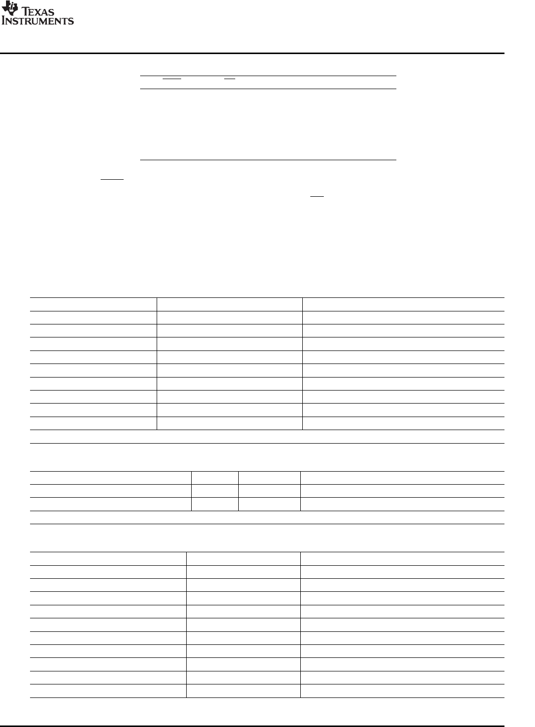
Table 3. TAS5352 Warning/Error Signal Decoding
OTW SD Device Condition
0 0 High-temperature error and/or high
current error
0 1 High-temperature warning
1 0 Undervoltage lockout or high-current
error
1 1 Normal operation, no errors/warnings
The temperature warning signals at the TAS5352DDV6EVM board are wired-OR to one temperature
warning signal ( OTW – pin 22 in control interface connector).
The shutdown signals are wired-OR into one shutdown signal ( SD – pin 20 in control interface connector).
The shutdown signals together with the temperature warning signal give chip state information as
described in Table 3 . Device fault-reporting outputs are open-drain outputs.
Table 4. General Test Conditions
General Test Conditions Notes
Output stage supply voltage: 34.5 V Laboratory power supply (EA-PS 7065-10A)
Load impedance BTL: 4-8 Ω
Load impedance PBTL: 2-4 Ω
Input signal 1 kHz sine
Sampling frequency 48 kHz
Gain setting in TAS5518 0 dB
Measurement filter AES17 and AUX0025
TI Input Board Input-USB 2 Rev 1
EVM configuration file Ver 1.00 TAS5352DDV6EVM Configuration (1.00).cfg
Note: These test conditions are used for all tests, unless otherwise specified.
Table 5. TAS5518 Register Settings
Register Register Value Notes
Modulation Index Limit Register 0x16 0x02 Set Modulation Index to 97.7%
Master Volume Register 0xD9 0x00 00 00 48 Master Volume set to 0 dB
Note: These register settings are used for all test, unless otherwise specified
Table 6. Electrical Data
Electrical Data Notes/Conditions
Output power, BTL, 4 Ω : 107 W 1 kHz, unclipped (0dBFS), T
A
= 25 ° C
Output power, BTL, 4 Ω : 140 W 1 kHz, 10% THD+N, T
A
= 25 ° C
Output power, BTL, 6 Ω : 78 W 1 kHz, unclipped (0 dBFS), T
A
= 25 ° C
Output power, BTL, 6 Ω : 103 W 1 kHz, 10% THD+N, T
A
= 25 ° C
Output power, BTL, 8 Ω : 61 W 1 kHz, unclipped (0 dBFS), T
A
= 25 ° C
Output power, BTL, 8 Ω : 80 W 1 kHz, 10% THD+N, T
A
= 25 ° C
Output power, BTL, 2 Ω : 209 W 1 kHz, unclipped (0 dBFS), T
A
= 25 ° C
Output power, BTL, 2 Ω : 268 W 1 kHz, 10% THD+N, T
A
= 25 ° C
Output power, BTL, 3 Ω : 152 W 1 kHz, unclipped (0 dBFS), T
A
= 25 ° C
Output power, BTL, 3 Ω : 200 W 1 kHz, 10% THD+N, T
A
= 25 ° C
SLAU244 – March 2008 TAS5352DDV6EVM 9
Submit Documentation Feedback