
Datasheet


Table Of Contents
- 1 Overview
- 2 Quick Setup Guide
- 3 Protection
- 4 TAS5352DDV6EVM Performance
- 4.1 THD+N vs Power (BTL – 4 )
- 4.2 THD+N vs Power (BTL – 6 )
- 4.3 THD+N vs Power (BTL – 8 )
- 4.4 THD+N vs Power (PBTL – 2 )
- 4.5 THD+N vs Power (PBTL – 3 )
- 4.6 THD+N vs Frequency (BTL –4 )
- 4.7 THD+N vs Frequency (BTL –6 )
- 4.8 THD+N vs Frequency (BTL –8 )
- 4.9 THD+N vs Frequency (PBTL – 2 )
- 4.10 THD+N vs Frequency (PBTL – 3 )
- 4.11 FFT Spectrum With –60-dBFS Tone (BTL)
- 4.12 FFT Spectrum With –60-dBFS Tone (PBTL)
- 4.13 Idle Noise FFT Spectrum (BTL)
- 4.14 Idle Noise FFT Spectrum (PBTL)
- 4.15 Channel Separation
- 4.16 Frequency Response (BTL)
- 4.17 Frequency Response (PBTL)
- 4.18 High-Current Protection (BTL)
- 4.19 High-Current Protection (PBTL)
- 4.20 Pop/Click (BTL)
- 4.21 Pop/Click (PBTL)
- 4.22 Output Stage Efficiency
- 4.23 Subwoofer Lineout THD vs Output Voltage
- 4.24 Subwoofer Lineout THD+N vs Frequency
- 4.25 Subwoofer Lineout Frequency Response
- 5 Related Documentation from Texas Instruments
- Appendix A Design Documents
www.ti.com
3 Protection
3.1 Short-Circuit Protection and Fault-Reporting Circuitry
3.2 Fault Reporting
Protection
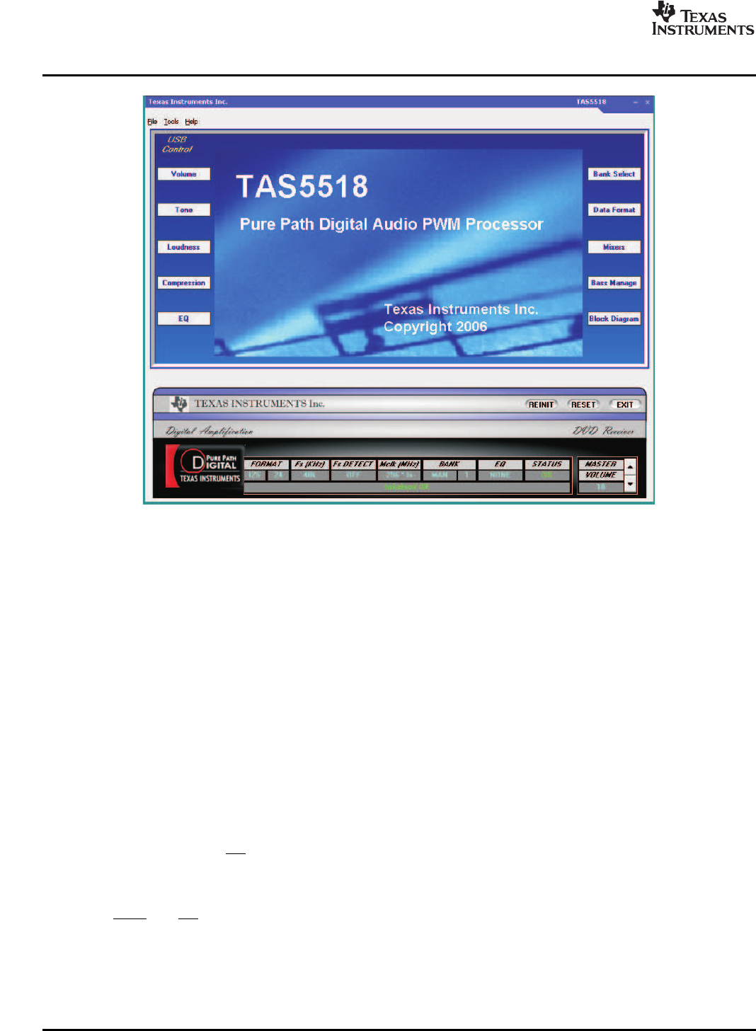
Figure 3. TAS5518 GUI Window
From the files menu, load the configuration file:
TAS5352DDV6EVM Configuration (1.00).cfg
The file is located on the PurePath CD-ROM. This file contains all settings for a default setup of the EVM.
For easy access of the file, it is recommended to copy the files into the directory where the GUI is
installed. The default location is C:\Program Files\Texas Instruments Inc\TAS5518\
For more advanced use of the GUI, see the GUI User’s Guide and data sheet for the TAS5518 device.
This section describes the short-circuit protection and fault reporting circuitry of the TAS5352 device.
The TAS5352 is a self-protecting device that provides fault reporting (including high-temperature
protection and short-circuit protection). The TAS5352 is configured in back-end auto-recovery mode and
therefore resets automatically after all errors (M1, M2, and M3 is set low); see the data sheet for further
explanation. This means that the device re-starts itself after an error occasion and reports shortly
thereafter through the SD error signal.
The OTW and SD outputs from TAS5352 indicate fault conditions. See the TAS5352 data sheet for a
description of these pins.
TAS5352DDV6EVM 8 SLAU244 – March 2008
Submit Documentation Feedback