Datasheet
Manuals
Brands
TEXAS INSTRUMENTS Manuals
Dev Kits
PCB design board
21
22
23
24
25
26
27
28
29
30
Table Of Contents
1 Overview
1.1 TAS5142DDV6EVM2 Features
1.2 PCB Key Map
2 Quick Setup Guide
2.1 Electrostatic Discharge Warning
2.2 Unpacking the EVM
2.3 Power-Supply Setup
2.4 Speaker Connection
2.5 GUI Software Installation
3 Protection
3.1 Short-Circuit Protection and Fault Reporting Circuitry
3.2 Fault Reporting
4 TAS5142DDV6EVM2 Performance
5 Related Documentation from Texas Instruments
5.1 Additional Documentation
Appendix A Design Documents
A.1 TAS5142DDV6EVM2 Schematic
A.2 TAS5142DDV6EVM2 Parts List
A.3 TAS5142DDV6EVM2 PCB Specification (Version 4.00)
A.4 TAS5142DDV6EVM2 PCB Layers
A.5 Heat Sink Drawing
A.6 Engineering Change Order
Important Notices
K002
www.ti.com
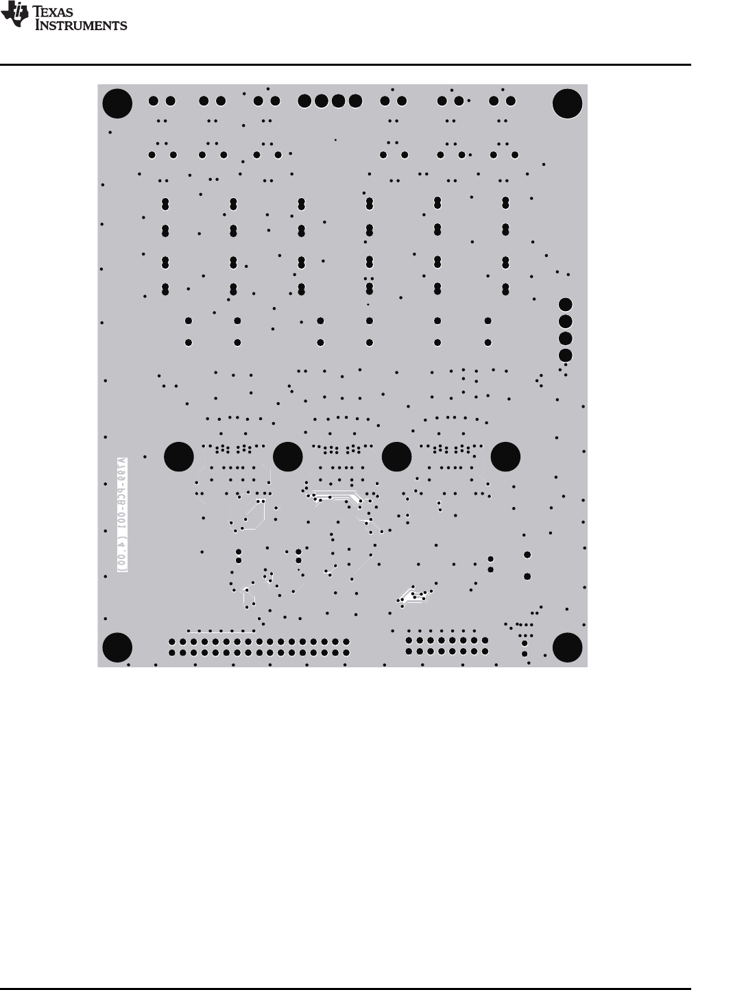
TAS5142DDV6EVM2
PCB
Layers
Figure
A-9.
Solder
Side
SLLU095A
–
April
2007
–
Revised
April
2008
Design
Documents
27
Submit
Documentation
Feedback
1
...
...
25
26
27
28
29
...
...
34