TAS5110D6REF Reference Design for the TAS5110DAD Digital Audio PWM Power Output Stage User’s Guide July 2003 Digital Audio/Application SLEU032
IMPORTANT NOTICE Texas Instruments Incorporated and its subsidiaries (TI) reserve the right to make corrections, modifications, enhancements, improvements, and other changes to its products and services at any time and to discontinue any product or service without notice. Customers should obtain the latest relevant information before placing orders and should verify that such information is current and complete.
EVM IMPORTANT NOTICE Texas Instruments (TI) provides the enclosed product(s) under the following conditions: This evaluation kit being sold by TI is intended for use for ENGINEERING DEVELOPMENT OR EVALUATION PURPOSES ONLY and is not considered by TI to be fit for commercial use.
EVM WARNINGS AND RESTRICTIONS It is important to operate this EVM within the specified input and output ranges described in the EVM User’s Guide. Exceeding the specified input range may cause unexpected operation and/or irreversible damage to the EVM. If there are questions concerning the input range, please contact a TI field representative prior to connecting the input power.
Information About Cautions and Warnings Preface Read This First About This Manual This manual describes the operation of the TAS5110D6REF evaluation module from Texas Instruments.
Related Documentation From Texas Instruments Related Documentation From Texas Instruments The following is a list of data manual that have detailed descriptions of the integrated circuits used in the design of the TAS5110D6REF evaluation module. The data manuals can be obtained at the URL http://www.ti.com.
Contents Contents 1 Introduction . . . . . . . . . . . . . . . . . . . . . . . . . . . . . . . . . . . . . . . . . . . . . . . . . . . . . . . . . . . . . . . . . . . . . 1.1 TAS5110D6REF Features . . . . . . . . . . . . . . . . . . . . . . . . . . . . . . . . . . . . . . . . . . . . . . . . . . . 1.2 PCB Key Map . . . . . . . . . . . . . . . . . . . . . . . . . . . . . . . . . . . . . . . . . . . . . . . . . . . . . . . . . . . . . . 1.3 Short-Circuit Protection and Fault Reporting Circuitry . . . . . .
Contents Figures 1–1 1–2 1–3 2–1 2–2 2–3 2–4 2–5 3–1 3–2 3–3 3–4 3–5 3–6 3–7 3–8 TDAA System With TAS5026REF/TAS5036 and TAS5110D6REF Modules . . . . . . . . . . . Physical Structure for the TAS5110D6REF (Rough Outline) . . . . . . . . . . . . . . . . . . . . . . . . . Auto Recovery Loop . . . . . . . . . . . . . . . . . . . . . . . . . . . . . . . . . . . . . . . . . . . . . . . . . . . . . . . . . . . Recommended TAS5110 Power-Up Sequence . . . . . . . . . . . . . . . . . . . . . . . . . . . . . . . . .
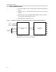
Chapter 1 Introduction The true digital audio amplifiers (TDAA) system consists of a PCM–PWM modulator device and a PWM power output device. The PCM–PWM processor accepts a serial PCM digital audio stream and converts it to a 3.3-V PWM audio stream. The TDAA output stage provides a large-signal PWM output. The digital PWM signal is then demodulated providing power output for driving loudspeakers.
TAS5110D6REF Features 1.1 TAS5110D6REF Features - Six channel TDAA reference design (double-sided plated-through PCB layout) - Supports noiseless self-contained protection system (short circuit and thermal) - Supports both two-level modulation (AD-modulation scheme) and three- level modulation (BD-modulation scheme) - Onboard subwoofer output (line level) Figure 1–1.
PCB Key Map 1.2 PCB Key Map The physical structure for the TAS5110D6REF is illustrated in Figure 1–2. Figure 1–2. Physical Structure for the TAS5110D6REF (Rough Outline) Output Stage Channel 5 Center Speaker Output Stage Channel 4 Right Rear Speaker Output Stage Channel 3 Left Rear Speaker Output Stage Channel 2 Right Front Speaker Output Stage Channel 1 Left Front Speaker PSU Interface J150 J160 PSU Control Interface 3.
PCB Key Map 1.3 Short-Circuit Protection and Fault Reporting Circuitry The TAS5110 is a self-protecting device that provides device fault reporting (including over-temperature protect and short-circuit protection). 1.3.1 Device Fault Reporting The ERR0, ERR1, and SHUTDOWN outputs from TAS5110 indicates the device conditions shown in Table 1–1. The device fault reporting outputs are open-drain outputs. Table 1–1. Device Fault Reporting 1.3.
PCB Key Map - H-bridge outputs (OUTPUTA and OUTPUTB) are in a high-impedance state (Hi-Z state). - ERR_RCVY at the PWM processor is forced low by the SHUTDOWN signal. - RESET at the TAS5110 is forced low by the VALID signal. - The VALID signal goes high after 4 ms and then the TAS5110 starts switching again. Figure 1–3.
1-6
Chapter 2 System Interfaces This chapter describes the TAS5110D6REF system interfaces. Topic Page 2.1 PSU Interface (J150) . . . . . . . . . . . . . . . . . . . . . . . . . . . . . . . . . . . . . . . . . . . 2-2 2.2 PSU Control Interface (J160) . . . . . . . . . . . . . . . . . . . . . . . . . . . . . . . . . . . 2-3 2.3 Loudspeaker Connectors (J240, J280, J340, J440, and J480) . . . . . 2-3 2.4 PWM Interface (J100) . . . . . . . . . . . . . . . . . . . . . . . . . . . . . . . . . . . . . . . .
PSU Interface (J150) 2.1 PSU Interface (J150) The TAS5110D6DAD board must be powered from external power supplies. High-end audio performance requires a stabilized power supply with low ripple voltage and low output impedance. Note: The length of the power-supply cable must be minimized. Increasing the impedance of the PSU cable is equal to increasing the distortion for the amplifier at high output levels and low frequencies. The maximum output stage supply voltage depends on the speaker load resistance.
PSU Control Interface (J160) 2.2 PSU Control Interface (J160) This interface is not used in this board. Figure 2–3. Pin Numbers at the PSU Control Interface 5 4 3 2 1 Table 2–2. PSU Control Interface Pin Connections Pin No. Pin Description Net Name at TAS5110D6REF Schematic 1 For future use 2 For future use 3 Ground GND 4 System reset (bidirectional) RESET 5 For future use V-HBRIDGE-CONTROL 2.3 Loudspeaker Connectors (J240, J280, J340, J380, J440, and J480) Figure 2–4.
PWM Interface (J100) 2.4 PWM Interface (J100) This interface connects the TAS5110D6REF board to the PWM processor module (e.g., TAS5026REF). Figure 2–5. Pin Numbers at PWM Interface (J100) 2 4 6 8 10 12 14 16 18 20 22 24 26 28 30 32 34 36 38 40 42 44 46 48 50 1 3 5 7 9 11 13 15 17 19 21 23 25 27 29 31 33 35 37 39 41 43 45 47 49 Connector: 50 positions, 2,54-mm pitch, double row IDC connector (Multicomp MC9A12–5034). Table 2–4. J100 Pin Description Pin No.
PWM Interface (J100) Table 2–4. J100 Pin Description (Continued) Pin No.
2-6
Chapter 3 Electrical Specifications and Typical Characteristics Graphs This chapter contains the electrical specifications and the typical characteristics graphs. Topic Page 3.1 Electrical Specifications . . . . . . . . . . . . . . . . . . . . . . . . . . . . . . . . . . . . . . . 3-2 3.2 Physical Specifications . . . . . . . . . . . . . . . . . . . . . . . . . . . . . . . . . . . . . . . . 3-2 3.3 Typical Characteristics Graphs . . . . . . . . . . . . . . . . . . . . . . . . . . . . . . . . .
TAS5110D6REF Electrical Specifications 3.1 TAS5110D6REF Electrical Specifications General Test Conditions PARAMETER Output stage power supply TEST CONDITIONS MIN TYP Laboratory power supply (EA–PS 7065–10A) Gate drive power supply Load impedance UNIT 26.5 VDC 26.5 VDC Ω 6 S/PDIF sampling frequency PWM processor MAX 48 kHz TAS5026REF (Rev 5) board Electrical Data Maximum output power (10% THD) 10% THD+N, 1 kHz, TA = 25°C, 6 Ω 50/channel W Maximum output power (unclipped) 0.
Typical Characteristics Graphs 3.3 Typical Characteristics Graphs Figure 3–1. THD+N vs Power – Channel 1, 2, 3, 4, 5, and 6 10 Power Supply = 26.5 V DC Load = 6 Ω Sample Frequency = 48 kHz Filter = AES17 5 2 1 0.5 % 0.2 0.1 Channel 3 0.05 Channel 6 Channel 5 Channel 2 0.02 Channel 1 Channel 4 0.01 60m 100m 200m 500m 2 1 5 10 20 50 Figure 3–2. THD+N vs Frequency – Channel 1 10 Power Supply = 26.5 V DC Input Signal = 1 kHz Load = 6 Ω Sample Frequency = 48 kHz Filter = AES17 5 2 1 0.
Typical Characteristics Graphs Figure 3–3. FFT With –60 dB Input Signal – Channel 1 +0 –5 –10 –15 –20 –25 –30 –35 –40 –45 –50 –55 –60 d B –65 r –70 A –75 –80 –85 –90 –95 –100 –105 –110 –115 –120 –125 –130 –135 –140 Power Supply = 26.5 V DC Input Signal = 1 kHz Load = 6 Ω Sample Frequency = 48 kHz Filter = AES17 FFT Size = 16 kΩ Reference = 15.8 V = Full Scale 0 1 1k 2k 3k 4k 5k 6k 7k 8k 9k 10k 11k 12k 13k 14k 15k 16k 17k 18k 19k 20k 21k 22k Frequency – Hz Figure 3–4.
Typical Characteristics Graphs Figure 3–5. Channel Separation vs Frequency – Channel 1 +20 +15 +10 +5 +0 Channel 1 –5 –10 –15 –20 Power Supply = 26.5 V DC Load = 6 Ω Sample Frequency = 48 kHz Filter = AES17 Reference = 15.8 V = Full Scale Input Left Channel = 0 FS Input Right Channel = 1 FS –25 –30 d –35 B r –40 A –45 –50 –55 –60 –65 Channel 2 –70 –75 –80 –85 –90 –95 –100 20 50 100 200 500 1k 2k Frequency – Hz 5k 10k 20k 30k Figure 3–6.
Typical Characteristics Graphs 10 9 8 7 Power Supply = 26.5 V DC Input Signal = 1 kHz, 1/39 duty cycle, attenuated to 39% of full scale Sample Frequency = 48 kHz 6 5 4 3 C U R R E N T A 2 1 1-Ω Load 0 –1 –2 –3 –4 –5 –6 –7 –8 –9 –10 38m 3-6 38.5m 39m 39.5m 40m 40.5m 41m 41.
Chapter 4 Schematic, Parts List, PCB Specification, and PCB Layout The chapter contains the schematic, parts list, PCB specification, and PCB layout for the TAS5110D6REF.
INPUT SECTION TI DIGITAL AUDIO GROUP ALL RIGHTS RESERVED - PATENTS PENDING TEXAS INSTRUMENTS INCORPORATED TAS5110D6REF
Front Speakers TI DIGITAL AUDIO GROUP ALL RIGHTS RESERVED - PATENTS PENDING TEXAS INSTRUMENTS INCORPORATED TAS5110D6REF Patents pending in circuitry design and layout (WO99/59241 & WO99/59242). This circuitry may only be used together with the integrated circuit TAS5100/TAS5110 from Texas Instruments Incorporated.
Rear Speakers TI DIGITAL AUDIO GROUP ALL RIGHTS RESERVED - PATENTS PENDING TEXAS INSTRUMENTS INCORPORATED TAS5110D6REF Patents pending in circuitry design and layout (WO99/59241 & WO99/59242). This circuitry may only be used together with the integrated circuit TAS5100/TAS5110 from Texas Instruments Incorporated.
Center Speaker & Subwoofer TI DIGITAL AUDIO GROUP ALL RIGHTS RESERVED - PATENTS PENDING TEXAS INSTRUMENTS INCORPORATED TAS5110D6REF Patents pending in circuitry design and layout (WO99/59241 & WO99/59242). This circuitry may only be used together with the integrated circuit TAS5100/TAS5110 from Texas Instruments Incorporated.
TAS5110D6REF Parts List Ref Des Part Number R121 R122 R131 R133 R140 R141 R117 R118 R124 R125 R126 R130 R132 R110 R111 R116 R170 R240 R241 R280 R282 R340 R341 R380 R382 R440 R441 R480 R482 R200 R201 R220 R221 R300 R301 R320 R321 R400 R401 100210000 100210000 100210000 100210000 100210000 100210000 100210010 100210010 100210010 100210010 100210010 100210010 100210010 100210020 100210020 100210030 100210030 100210080 100210080 100210080 100210080 100210080 100210080 100210080 100210080 100210080 100210080
TAS5110D6REF Parts List Ref Des Part Number R420 R421 R202 R203 R222 R223 R302 R303 R322 R323 R402 R403 R422 R423 R120 R114 R115 R123 R260 R360 R460 R112 R113 R204 R205 R224 R225 R304 R305 R324 R325 R404 R405 R424 R425 C202 C203 C205 C207 100210090 100210090 100213020 100213020 100213020 100213020 100213020 100213020 100213020 100213020 100213020 100213020 100213020 100213020 100222000 100222020 100222020 100233000 100233080 100233080 100233080 100247020 100247020 100315080 100315080 100315080 100315080
TAS5110D6REF Parts List Ref Des Part Number C208 C222 C223 C225 C227 C302 C303 C305 C307 C308 C322 C323 C325 C327 C328 C402 C403 C405 C407 C408 C422 C423 C425 C427 C428 C429 R228 C204 C206 C224 C226 C304 C306 C324 C326 C404 C406 C424 C426 200011040 200011040 200011040 200011040 200011040 200011040 200011040 200011040 200011040 200011040 200011040 200011040 200011040 200011040 200011040 200011040 200011040 200011040 200011040 200011040 200011040 200011040 200011040 200011040 200011040 200011040 200011040
TAS5110D6REF Parts List Ref Des Part Number C100 C101 C115 C117 C170 C172 C150 C245 C246 C263 C285 C286 C345 C346 C363 C385 C386 C445 C446 C463 C485 C486 C114 C116 C171 C173 C201 C221 C301 C321 C401 C421 C110 C111 C112 C113 C200 C220 C300 200041060 200041060 200041060 200041060 200041060 200041060 200044750 200051030 200051030 200051030 200051030 200051030 200051030 200051030 200051030 200051030 200051030 200051030 200051030 200051030 200051030 200051030 200051040 200051040 200051040 200051040 200051040
TAS5110D6REF Parts List Ref Des Part Number C320 C400 C420 C130 C131 C140 C141 C262 C362 C462 C260 C261 C360 C361 C460 C461 C240 C241 C280 C281 C340 C341 C380 C381 C440 C441 C480 C481 L240 L241 L280 L281 L340 L341 L380 L381 L440 L441 L480 200061010 200061010 200061010 200061020 200061020 200061020 200061020 200061020 200061020 200061020 250041081 250041081 250041081 250041081 250041081 250041081 270021051 270021051 270021051 270021051 270021051 270021051 270021051 270021051 270021051 270021051 270021051
TAS5110D6REF Parts List Ref Des Part Number L481 LED121 LED122 LED123 LED120 Q120 Q121 Q122 U200 U220 U300 U320 U400 U420 U111 U110 U130 U140 U170 MECH1 MECH2 MECH2 SCREW01 SCREW02 SCREW03 SCREW04 SCREW05 SCREW06 WASHER01 WASHER02 WASHER03 WASHER04 WASHER05 WASHER06 J110 J160 J240 J280 J340 350101031 405000810 405000810 405000820 405000830 425229070 425229070 425229070 500051101 500051101 500051101 500051101 500051101 500051101 510102721 520141261 520141261 520141261 540251330 600100050 600100060 6001000
TAS5110D6REF Parts List Ref Des Part Number J380 J440 J480 J150 J100 PCB C132 C133 C134 C209 C229 C309 C329 C409 C242 C243 C244 C282 C283 C284 C342 C343 C344 C382 C383 C384 C442 C443 C444 C482 C483 C484 J101 J102 R261 R262 L260 L261 L262 700300020 700300020 700300020 700300040 700820500 900116710 Deleted Deleted Deleted Deleted Deleted Deleted Deleted Deleted Not used Not used Not used Not used Not used Not used Not used Not used Not used Not used Not used Not used Not used Not used Not used Not used Not
TAS5110D6REF Parts List Ref Des Part Number L263 L360 L361 L362 L363 L460 L461 L462 L463 Trace Trace Trace Trace Trace Trace Trace Trace Trace P167-LST-001(4.
TI TAS5110D6REF PCB SPECIFICATION (1.00) Claus Reckweg TAS5110D6REF PCB SPECIFICATION BOARD IDENTIFICATION: P167-PCB-001 (1.