
Instruction Manual


2-5
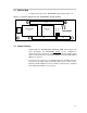
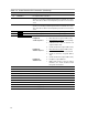
2.3 PWM Interface (J140)
The PWM interface connects the TAS5026REF board to the output stage
module.
Figure 2–1. Pin Numbers at PWM Interface (J140)
2
31 5
64 8
97
10 12
1311 15
1614 18
1917
20 22
2321 25
2624 28
2927
30 32
3331 35
3634 38
3937
40 42
4341 45
4644 48
4947
50
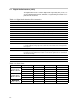
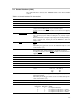
Table 2–4.J140 Pin Description
Pin No. Net Name Description
01 V-HBRIDGE-CONTROL For future use
02 GND Ground
03 PWM–AP–1
Channel 1 PWM input (differential +) – positive H-bridge side
04 PWM–AM–1 Channel 1 PWM input (differential –) – positive H-bridge side
05 VALID–1 Valid channel 1
06 PWM–BM–1 Channel 1 PWM input (differential –) – negative H-bridge side
07 PWM–BP–1 Channel 1 PWM input (differential +) – negative H-bridge side
08 GND Ground
09 PWM–AP–2 Channel 2 PWM input (differential +) – positive H-bridge side
10 PWM–AM–2 Channel 2 PWM input (differential –) – positive H-bridge side
11 VALID–2 Valid channel 2
12 PWM–BM–2 Channel 2 PWM input (differential –) – negative H-bridge side
13 PWM–BP–2 Channel 2 PWM input (differential +) – negative H-bridge side
14 GND Ground
15 PWM–AP–3 Channel 3 PWM input (differential +) – positive H-bridge side
16 PWM–AM–3 Channel 3 PWM input (differential –) – positive H-bridge side
17 VALID–3 Valid channel 3
18 PWM–BM–3 Channel 3 PWM input (differential –) – negative H-bridge side
19 PWM–BP–3 Channel 3 PWM input (differential +) – negative H-bridge side
20 GND Ground
21 PWM–AP–4 Channel 4 PWM input (differential +) – positive H-bridge side
22 PWM–AM–4 Channel 4 PWM input (differential –) – positive H-bridge side
23 VALID–4 Valid channel 4
24 PWM–BM–4 Channel 4 PWM input (differential –) – negative H-bridge side
25 PWM–BP–4 Channel 4 PWM input (differential +) – negative H-bridge side
26 GND Ground
27 PWM–AP–5 Channel 5 PWM input (differential +) – positive H-bridge side