
Instruction Manual


2-4
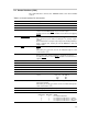
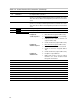
Table 2–3. Control Interface Pin Connections (Continued)
Pin No. Net Name Description
19 DEM-SEL1 De-emphasis filter select bit 1
20 SD–E1 Shutdown error reporting group 1. The TAS51XX digital output stages
(channel 1, 2, and 5) assert this signal low when an internal error occurs.
This can be due to either an overtemperature protection or an overcurrent
event.
21 SD–E2 Shutdown error reporting group 2. The TAS51XX digital output stages
(channel 3, 4, and 6) assert this signal low when an internal error occurs.
This can be due to either an overtemperature protection or an overcurrent
event.
22 ERROR0 Error reporting 0 (ERR0 from the TAS51XX output stages)
23 ERROR1 Error reporting 1 (ERR1 from the TAS51XX output stages)
24 HEADPHONE–DISABLE
Headphone control
Headphone
1. Mute all channels (register address 03h)
enable sequence
2. HEADPHONE–DISABLE
is asserted high.
3. Individual channel mute of channels 3–6
(register address 19h).
4. Unmute all channels (register address 03h).
Headphone
1. Mute all channels (register address 03h)
disable sequence
2. HEADPHONE–DISABLE
is asserted low.
3. Unmute of channels 3–6 (register address
19h).
4. Unmute all channels (register address 03h).
Headphone
0 Headphone output disabled.
disable mode
1 Output stage channel 1 and 2 is muted.
Channel 3, 4, 5, and 6 should be muted
through the I
2
C interface.
25
GND Ground
26 GND Ground
27 Not used For future use
28 Not used For future use
29 Not used For future use
30 Not used For future use
31 GND Ground
32 GND Ground
33 +5V Power supply (out)
34 +5V Power supply (out)