
Instruction Manual


2-3
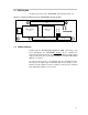
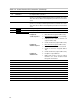
2.2 Control Interface (J100)
The control interface connects the TAS5026 board to the microcontroller
section.
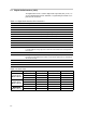
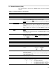
Table 2–3.Control Interface Pin Connections
Pin No. Net Name Description
01 GND Ground
02 V-HBRIDGE-CONTROL Not used
03 GND
Ground
04 RESET System reset (bidirectional). The TAS5026 enters a 4-ms initiation
sequence before PWM signals are present at the output.
If a quit reset is desired, MUTE should be asserted low before applying
RESET
.
05 SOFT–RESET TAS5026 error recovery (active low). Enables the user to enter a reset
state click and pop free without resetting the I
2
C (volume) register
settings.
Both soft and hard resets stop the output stage from switching and brings
it into a low-low state, meaning the low-side MOSFET in both half
bridges is ON.
06 MUTE MUTE (active low) ramps the volume from any setting to noiseless soft
mute.
Alternatively, the mute mode can also be initiated through the serial
control interface (I
2
C).
07 POWER–DOWN POWER–DOWN (active low) places the TAS5026 in power-down mode.
During power down, all I
2
C and data bus operations are ignored.
If a quit power down is desired, MUTE
should be asserted low before
applying RESET
.
08 Not used
09 Not used
10 SDA I
2
C data clock
11 GND Ground
12 SCL I
2
C bit clock
13 Not used
14 I2C–ADDRESS–SELECT TAS5026 I
2
C address
select:
Pin Level
Low
High
I
2
C Address
1Ah
1Bh
15 DOUBLE–SPEED DOUBLE–SPEED (active high) is used to support sampling rates of
88.2 kHz and 96 kHz.
Alternatively, the double-speed mode can also be initiated through the
serial control interface (I
2
C).
16 CLIP Digital clipping indicator (active low)
17 GND Ground
18 DEM-SEL2
De-emphasis filter select bit 1
DEM-SEL2
0
0
1
1
DEM-SEL1
0
1
0
1
MODE
De-emphasis disabled
De-emphasis enabled for Fs = 32 kHz
De-emphasis enabled for Fs = 44.1 kHz
De-emphasis enabled for Fs = 48 kHz