
Instruction Manual


2-2
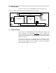
2.1 Digital Audio Interface (J160)
The digital audio interface contains digital audio signal data (I2S), clocks, etc.
See the TAS5026 data manual, SLES041, for signal timing and details not ex-
plained in this document.
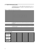
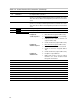
Table 2–1.Digital Audio Interface Pin Connections
Pin No. Net Name Description
01 GND Ground
02 MCLK-IN Not used
03 GND
Ground
04 SDIN1 I2S data 1, channel 1 and 2 (left and right front speakers)
05 SDIN2 I2S data 2, channel 3 and 4 (left and right rear speakers)
06 SDIN3 I2S data 3, channel 5 and 6 (center speaker subwoofer)
07 GND Ground
08 GND Ground
09 GND Ground
10 GND Ground
11 SCLK I2S bit clock (64xFs) used to shift in serial data from SIN1, SDIN2, and SDIN3. SDATA
is sampled with the rising edge of the SCLK. The I2S format can be changed in the
I
2
C registers.
12 GND Ground
13 LRCLK Left/right clock (Fs) used to indicate left/right data being transmitted in SDATA. The
left channel is transmitted when LRCLK is low and the right channel is transmitted
when LRCLK is high.
14 GND Ground
15 Not used For future use
16 GND Ground
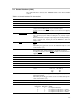
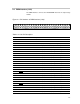
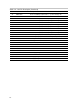
Table 2–2.Clock Rates
Sample Frequency LRCLK (Fs) SCLK (64 × Fs) MCLK
32 kHz 32 kHz 2.048 MHz 8.192 MHz
Normal Speed
×
44.1 kHz 44.1 kHz 2.8224 MHz 11.2896 MHz
MCLK = 256 × Fs
48 kHz 48 kHz 3.072 MHz 12.288 MHz
64 kHz 64 kHz 4.096 MHz 16.384 MHz
Double Speed
×
88.2 kHz 88.2 kHz 5.6448 MHz 22.5792 MHz
MCLK = 256 × Fs
96 kHz 96 kHz 6.144 MHz 24.576 MHz
Quad Speed
176.4 kHz 176.4 kHz 11.2896 MHz 22.579 MHz
Quad Speed
MCLK = 128 × Fs
192 kHz 192 kHz 12.288 MHz 24.576 MHz