
Datasheet


De-Emph sa is
F tei rl
Interpolation
F tei rl
Decimation
F tei rl
Re-Sampler
Rate
Es matorti
f
SIN
f
SOUT
R feree nceClock
P rtAo
P rtBo
DIR
Audio DataOutput
INT_ YS NC
From PortA,Port B,orDIT
SRCIS[1:0]
DEM[ :1 0]
AUTODEM
IGRP[1:0]
SRI[ :4 0]
SRF[10:0]
R IA OT
RDY (pin15)
M TE(U pin14)
DDN
T CR KA
AL[7:0]
AR[7:0]
OWL[ :1 0]
MC KL
R KX IC
R KX OC
SRCCLK[10: ]
SRC4392
www.ti.com
SBFS029D –DECEMBER 2005–REVISED DECEMBER 2012
ASYNCHRONOUS SAMPLE RATE CONVERTER (SRC) OPERATION
The asynchronous SRC provides conversion from an arbitrary input sampling rate to a desired output sampling
rate. The input and output sampling rates may be equal or different, within the bounds of a 1:16 to 16:1 input-to-
output sampling ratio range. The input and output data sources may be completely asynchronous to one another;
synchronous operation is also supported. The input-to-output sampling ratio is determined automatically using
internal rate estimation logic, with the re-sampler being updated in real time without the need for programming.
The SRC supports input and output sampling rates up to 216kHz, with audio data word lengths up to 24 bits. A
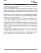
functional block diagram for the SRC is shown in Figure 72.
Figure 72. Asynchronous Sample Rate Converter (SRC) Functional Block Diagram
The SRC receives a digital audio input from one of three data sources: Port A, Port B, or the DIR. By default,
Port A is selected as the input source for the SRC. The output of the SRC may be connected to Port A, Port B,
and/or the DIT.
The SRC requires a reference clock, which may be sourced from either the MCLK (pin 25) or RXCKI (pin 13)
clock inputs, or from the RXCKO recovered master clock output from the DIR block. The reference clock is
utilized by the rate estimator to determine the input-to-output sampling ratio. By default, MCLK is selected as the
reference clock source for the SRC.
As part of the SRC rate estimation and re-sampling functions, two digital servo loops are employed, one for the
input side and one for the output side. The servo loops operate in two modes: Fast and Slow. When a change in
one or both of the sampling rates occurs, the servo loop(s) enter(s) Fast mode operation. When a servo loop has
settled in Fast mode, it will then switch to Slow mode. When both the input and output servo loops have switched
to Slow mode, the RDY output (pin 15) is forced low, indicating that the SRC has completed the rate estimation
process.
Copyright © 2005–2012, Texas Instruments Incorporated Submit Documentation Feedback 33
Product Folder Links: SRC4392