
Datasheet


Selecting an Input Source and an Output Port
3-6
When ~PORT = HI, the output of the DIT4192 digital audio transmitter (U5) at
connector J4 is selected as the output port. This port is designed to interface
to digital audio signal analyzers and devices that accept AES3 formatted digi-
tal audio data. This includes the S/PDIF inputs of A/V receivers and digital re-
cording devices.
When selecting the digital audio transmitter (U5) as the output port, the setting
of the OM/~S element of switch SW9 will correctly set the Master or Slave
mode for both the SRC419x and DIT4192 devices. The input data format of
the transmitter must be selected using the FMT0 and FMT1 elements of switch
SW3. The format must match the output data format of the SRC419x device,
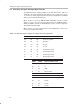
as described in Section 3.4 of this chapter. Table 3–4 summarizes the trans-
mitter format configuration options using switch SW3.
Table 3–4.Digital Audio Transmitter Input Data Format Configuration
FMT1 FMT0 Data Format
LO
LO
HI
HI
LO
HI
LO
HI
Left Justified, 16– to 24–Bits
Philips I
2
S, 16– to 24–Bits
Right Justified, 24–Bits
Right Justified, 16–Bits