
Datasheet


Selecting the Input & Output Data Formats
3-4
3.4 Selecting the Input & Output Data Formats
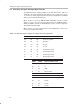
The SRC419x devices support a flexible set of audio data formats. Table 3–2
summarizes the input and output format options for the sample rate convert-
ers. Section 3.5 of this chapter describes the format configuration for the digital
audio receiver and transmitter devices.
When ~4193 is set to HI, the IFMT0, IFMT1 and IFMT2 elements of switch
SW7 are used to select the input port data format. The OFMT0, OFMT1,
OWL0, and OWL1 elements of switch SW10 are used to select the output port
data format and word length.
When ~4193 is set to LO, Control Register 3 of the SRC4193 is used to select
the input and output data formats.
Table 3–2.SRC419x Input & Output Port Data Format Configuration
IFMT2 IFMT1 IFMT0 Input Port Data Format
LO LO LO 24–Bit Left Justified
LO LO HI 24–Bit I
2
S
LO HI LO Unused
LO HI HI Unused
HI LO LO 16–Bit Right Justified
HI LO HI 18–Bit Right Justified
HI HI LO 20–Bit Right Justified
HI
HI HI 24–Bit Right Justified
OFMT1 OFMT0 Output Port Data Format
LO LO Left Justified
LO HI I
2
S
HI
HI
LO
HI
TDM
Right Justified
OWL1 OWL0 Output Port Data Word Length
LO LO 24–Bits
LO HI 20–Bits
HI
HI
LO
HI
18–Bits
16–Bits