
Datasheet


Selecting the Input & Output Port Modes
3-3
Setup Guide
3.3 Selecting the Input & Output Port Modes
The input and output ports of the SRC419x devices support seven modes
of operation. Table 3–1 summarizes the mode settings for the SRC419x
devices. In Master mode, the LRCK and BCK clocks are outputs, derived
from the reference clock (RCKI) input. In Slave mode, the LRCK and BCK
clocks are inputs, which are generated by the audio input or output device.
When ~4193 is set to HI, the port modes are selected using the MODE0,
MODE1, and MODE2 elements of switch SW10.
When ~SRC4193 is set to LO, the MODE[2:0] bits in Control Register 1 of
the SRC4193 are used to select the port modes.
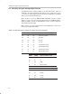
Table 3–1.SRC419x Input & Output Port Mode Selection
MODE2 MODE1 MODE0 Serial Port Mode
LO LO LO Both Input and Output Ports are in Slave mode
LO LO HI Output Port is in Master mode with RCKI = 128f
s
LO HI LO Output Port is in Master mode with RCKI = 512f
s
LO HI HI Output Port is in Master mode with RCKI = 256f
s
HI LO LO Both Input and Output Ports are in Slave mode
HI LO HI Input Port is in Master mode with RCKI = 128f
s
HI HI LO Input Port is in Master mode with RCKI = 512f
s
HI HI HI Input Port is in Master mode with RCKI = 256f
s